
Page 128 - Complete Wireless Design
P. 128
Amplifier Design
Amplifier Design 127
In interstage matching, it is possible to choose between two methodologies:
match the output impedance of the first stage (usually a “high” impedance) to
the input impedance of the second stage (usually a “low” impedance). This uses
the fewest components. Or, match everything to 50 ohms for standardization.
This permits the testing of the final physical design from stage to stage with
normal 50-ohm test gear.
Lumped L matching. The simple, but very popular, L matching network has a
disadvantage in that the Q of the circuit cannot be selected as it can in the
more complex networks shown below. A low Q is desired to increase the band-
width of the amplifier, as well as to decrease lossy circulating currents in power
amplifiers. Still, the value of Q is usually naturally low in an L network, and
thus will suffice for most semiwideband matching needs.
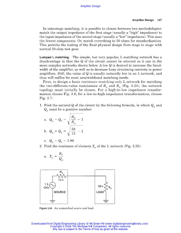
First, to design a basic resistance-matching-only L network for matching
the two-different-value resistances of R and R (Fig. 3.24), the network
S P
topology must initially be chosen. For a high-to-low impedance transfor-
mation choose Fig. 3.6; for a low-to-high impedance transformation, choose
Fig. 3.7:
1. Find the natural Q of the circuit by the following formula, in which Q and
S
Q must be a positive number:
P
R
P
a. Q Q 1
S P R
S
58
b. Q Q 1
S P 12
c. Q Q 1.96
S P
2. Find the reactance of element X of the L network (Fig. 3.25):
P
R
P
a. X
P Q
P
Figure 3.24 An unmatched source and load.
Downloaded from Digital Engineering Library @ McGraw-Hill (www.digitalengineeringlibrary.com)
Copyright © 2004 The McGraw-Hill Companies. All rights reserved.
Any use is subject to the Terms of Use as given at the website.