
Page 125 - Complete Wireless Design
P. 125
Amplifier Design
124 Chapter Three
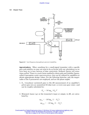
Figure 3.21 Low-frequency decoupling to prevent instability.
Approximations. When searching for a small-signal transistor with a specific
gain and stability, we may not want to be as formal with our calculations as we
have been up to now, because of time constraints. Ballpark figures will some-
times suffice. There is a much faster method to obtain gain and stability figures,
called S-parameter scalar approximations, that can be utilized for amplifiers to
obtain approximate design values. For the following formulas, only the magni-
tudes of the S parameters are employed, and not the phase angles.
1. G (transducer unilateral gain) is the dB measurement of an amplifier’s
tu
power gain into an unmatched 50-ohm load—a worst-case gain value—and
can be roughly calculated by:
G 10 log |S | 2
tu 10 21
2. Mismatch losses (
p) at the transistor’s input or output, in dB, are calcu-
lated by:
2
p 10 log (1 S )
IN 10 11
p 10 log (1 S 2 )
OUT 10 22
Downloaded from Digital Engineering Library @ McGraw-Hill (www.digitalengineeringlibrary.com)
Copyright © 2004 The McGraw-Hill Companies. All rights reserved.
Any use is subject to the Terms of Use as given at the website.