
Page 122 - Complete Wireless Design
P. 122
Amplifier Design
Amplifier Design 121
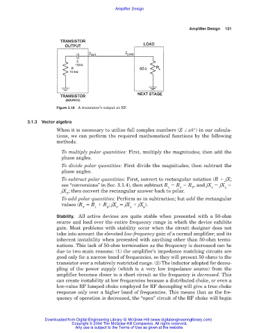
Figure 3.18 A transistor’s output at RF.
3.1.3 Vector algebra
When it is necessary to utilize full complex numbers (Z ± °) in our calcula-
tions, we can perform the required mathematical functions by the following
methods.
To multiply polar quantities: First, multiply the magnitudes; then add the
phase angles.
To divide polar quantities: First divide the magnitudes; then subtract the
phase angles.
To subtract polar quantities: First, convert to rectangular notation (R jX;
see “conversions” in Sec. 3.1.4), then subtract R R R , and jX jX
1 2 T 1 2
jX ; then convert the rectangular answer back to polar.
T
To add polar quantities: Perform as in subtraction; but add the rectangular
values (R R R ; jX jX jX ).
T 1 2 T 1 2
Stability. All active devices are quite stable when presented with a 50-ohm
source and load over the entire frequency range in which the device exhibits
gain. Most problems with stability occur when the circuit designer does not
take into account the elevated low-frequency gain of a normal amplifier; and its
inherent instability when presented with anything other than 50-ohm termi-
nations. This lack of 50-ohm termination as the frequency is decreased can be
due to two main reasons: (1) the amplifier’s impedance matching circuits are
good only for a narrow band of frequencies, so they will present 50 ohms to the
transistor over a relatively restricted range. (2) The inductor adopted for decou-
pling of the power supply (which is a very low impedance source) from the
amplifier becomes closer to a short circuit as the frequency is decreased. This
can create instability at low frequencies because a distributed choke, or even a
low-value RF lumped choke employed for RF decoupling will give a true choke
response only over a higher band of frequencies. This means that as the fre-
quency of operation is decreased, the “open” circuit of the RF choke will begin
Downloaded from Digital Engineering Library @ McGraw-Hill (www.digitalengineeringlibrary.com)
Copyright © 2004 The McGraw-Hill Companies. All rights reserved.
Any use is subject to the Terms of Use as given at the website.