
Page 127 - Complete Wireless Design
P. 127
Amplifier Design
126 Chapter Three
3.1.4 Matching networks
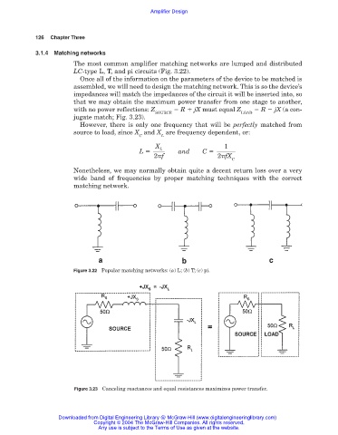
The most common amplifier matching networks are lumped and distributed
LC-type L, T, and pi circuits (Fig. 3.22).
Once all of the information on the parameters of the device to be matched is
assembled, we will need to design the matching network. This is so the device’s
impedances will match the impedances of the circuit it will be inserted into, so
that we may obtain the maximum power transfer from one stage to another,
with no power reflections: Z R jX must equal Z R jX (a con-
SOURCE LOAD
jugate match; Fig. 3.23).
However, there is only one frequency that will be perfectly matched from
source to load, since X and X are frequency dependent, or:
C L
X 1
L
L and C
2 f 2 fX
C
Nonetheless, we may normally obtain quite a decent return loss over a very
wide band of frequencies by proper matching techniques with the correct
matching network.
Figure 3.22 Popular matching networks: (a) L; (b) T; (c) pi.
Figure 3.23 Canceling reactances and equal resistances maximizes power transfer.
Downloaded from Digital Engineering Library @ McGraw-Hill (www.digitalengineeringlibrary.com)
Copyright © 2004 The McGraw-Hill Companies. All rights reserved.
Any use is subject to the Terms of Use as given at the website.