
Page 123 - Complete Wireless Design
P. 123
Amplifier Design
122 Chapter Three
to look more like a piece of straight wire than as a choke, causing the amplifi-
er to have a load that no longer appears as 50 ohms, which can create oscilla-
tions in a conditionally stable amplifier. One way to lessen this effect is to add
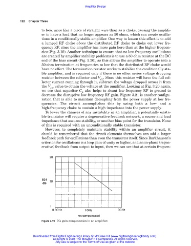
a lumped RF choke above the distributed RF choke to choke out lower fre-
quency RF, since the amplifier has more gain here than at the higher frequen-
cies (Fig. 3.19). Another technique to ensure that no low-frequency oscillations
are created by amplifier stability problems is to use a 50-ohm resistor at the DC
end of the bias circuit (Fig. 3.20), as this allows the amplifier to operate into a
50-ohm termination at frequencies so low that the distributed RF choke would
have no effect. The termination resistor works to stabilize the conditionally sta-
ble amplifier, and is required only if there is no other series voltage dropping
resistor between the collector and V . Since this resistor will have the full col-
CC
lector current running through it, subtract the voltage dropped across it from
the V value to obtain the voltage at the amplifier. Looking at Fig. 3.20 again,
CC
we see that capacitor C also helps to shunt low-frequency RF to ground to
B
decrease the disruptive low-frequency RF gain. Figure 3.21 is another configu-
ration that is able to maintain decoupling from the power supply at low fre-
quencies. The circuit accomplishes this by using both a low- and a
high-frequency choke to sustain a high impedance into the power supply.
To lower the chances of any instability in an amplifier, a potentially unsta-
ble transistor will require a degenerative feedback network, a source and load
impedance that assures stability, or another bias point for the transistor. None
of this is required with an unconditionally stable transistor.
However, to completely maintain stability within an amplifier circuit, it
should be remembered that the circuit elements themselves can add a larger
feedback path for oscillations than even the transistor itself. Since Barkhausen’s
criterion for oscillations is a loop gain of unity or higher, and an in-phase (regen-
erative) feedback from output to input, then we can see that at certain frequen-
Figure 3.19 No gain compensation in an amplifier.
Downloaded from Digital Engineering Library @ McGraw-Hill (www.digitalengineeringlibrary.com)
Copyright © 2004 The McGraw-Hill Companies. All rights reserved.
Any use is subject to the Terms of Use as given at the website.