
Page 335 - Complete Wireless Design
P. 335
Support Circuit Design
334 Chapter Eight
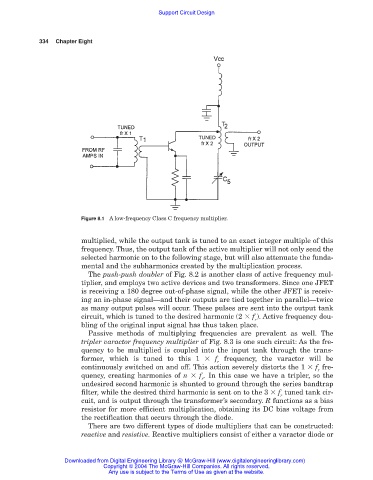
Figure 8.1 A low-frequency Class C frequency multiplier.
multiplied, while the output tank is tuned to an exact integer multiple of this
frequency. Thus, the output tank of the active multiplier will not only send the
selected harmonic on to the following stage, but will also attenuate the funda-
mental and the subharmonics created by the multiplication process.
The push-push doubler of Fig. 8.2 is another class of active frequency mul-
tiplier, and employs two active devices and two transformers. Since one JFET
is receiving a 180 degree out-of-phase signal, while the other JFET is receiv-
ing an in-phase signal—and their outputs are tied together in parallel—twice
as many output pulses will occur. These pulses are sent into the output tank
circuit, which is tuned to the desired harmonic (2 f ). Active frequency dou-
r
bling of the original input signal has thus taken place.
Passive methods of multiplying frequencies are prevalent as well. The
tripler varactor frequency multiplier of Fig. 8.3 is one such circuit: As the fre-
quency to be multiplied is coupled into the input tank through the trans-
former, which is tuned to this 1 f frequency, the varactor will be
r
continuously switched on and off. This action severely distorts the 1 f fre-
r
quency, creating harmonics of n f . In this case we have a tripler, so the
r
undesired second harmonic is shunted to ground through the series bandtrap
filter, while the desired third harmonic is sent on to the 3 f tuned tank cir-
r
cuit, and is output through the transformer’s secondary. R functions as a bias
resistor for more efficient multiplication, obtaining its DC bias voltage from
the rectification that occurs through the diode.
There are two different types of diode multipliers that can be constructed:
reactive and resistive. Reactive multipliers consist of either a varactor diode or
Downloaded from Digital Engineering Library @ McGraw-Hill (www.digitalengineeringlibrary.com)
Copyright © 2004 The McGraw-Hill Companies. All rights reserved.
Any use is subject to the Terms of Use as given at the website.