
Page 336 - Complete Wireless Design
P. 336
Support Circuit Design
Support Circuit Design 335
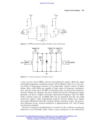
Figure 8.2 A JFET push-push frequency doubler circuit with biasing.
Figure 8.3 A varactor frequency multiplier circuit.
a step recovery diode (SRD), and are narrowband by nature. Both the input
and output impedance matching circuits will be effective only over a very nar-
row band of frequencies because of the inherently reactive nature of these
diodes. Also, while SRDs are capable of high values of frequency multiplica-
tion, and can reach up to 20 GHz in frequency, they are also quite expensive.
Varactor diodes are cheaper, but have much lower levels of frequency multi-
plication, yet have a higher maximum operational frequency than the SRD.
GaAs varactor types are available that can be operated into the very high
microwave region, while hyperabrupt snap-off varactor diodes have higher
conversion efficiencies than the common abrupt varactors; in fact, the conver-
sion efficiency of any varactor multiplier is approximately 1/N, with N being
the harmonic number.
Resistive frequency multiplication is created by the nonlinear resistance
inherent in any Schottky diode. Since a pure resistance is not affected by
Downloaded from Digital Engineering Library @ McGraw-Hill (www.digitalengineeringlibrary.com)
Copyright © 2004 The McGraw-Hill Companies. All rights reserved.
Any use is subject to the Terms of Use as given at the website.