
Page 341 - Complete Wireless Design
P. 341
Support Circuit Design
340 Chapter Eight
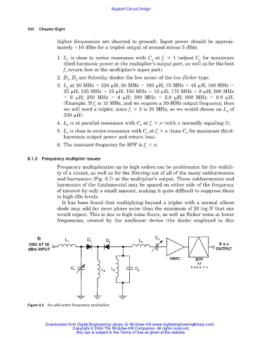
higher frequencies are shunted to ground). Input power should be approxi-
mately 10 dBm for a tripled output of around minus 5 dBm.
1. L is close to series resonance with C at f 1 (adjust C for maximum
1 1 r 1
third-harmonic power at the multiplier’s output port, as well as for the best
f return loss at the multiplier’s input port).
r
2. D , D are Schottky diodes (for low noise) of the low-flicker type.
1 2
3. L at 30 MHz 330 H; 50 MHz 100 H; 75 MHz 45 H; 100 MHz
4
25 H; 125 MHz 15 H; 150 MHz 10 H; 175 MHz 8 H; 200 MHz
6 H; 250 MHz 4 H; 300 MHz 2.8 H; 600 MHz 0.8 H.
(Example: If f is 10 MHz, and we require a 30-MHz output frequency, then
r
we will need a tripler, since f 3 is 30 MHz, so we would choose an L of
r 4
330 H).
4. L is at parallel resonance with C at f n (with n normally equaling 3).
2 2 r
5. L is close to series resonance with C at f n (tune C for maximum third-
3 3 r 3
harmonic output power and return loss).
6. The resonant frequency for BPF is f n.
r
8.1.3 Frequency multiplier issues
Frequency multiplication up to high orders can be problematic for the stabili-
ty of a circuit, as well as for the filtering out of all of the many subharmonics
and harmonics (Fig. 8.7) at the multiplier’s output. These subharmonics and
harmonics of the fundamental may be spaced on either side of the frequency
of interest by only a small amount, making it quite difficult to suppress them
to high dBc levels.
It has been found that multiplying beyond a tripler with a normal silicon
diode may add far more phase noise than the minimum of 20 log N that one
would expect. This is due to high noise floors, as well as flicker noise at lower
frequencies, created by the nonlinear device (the diode) employed in this
Figure 8.6 An odd-order frequency multiplier.
Downloaded from Digital Engineering Library @ McGraw-Hill (www.digitalengineeringlibrary.com)
Copyright © 2004 The McGraw-Hill Companies. All rights reserved.
Any use is subject to the Terms of Use as given at the website.