
Page 337 - Complete Wireless Design
P. 337
Support Circuit Design
336 Chapter Eight
frequency (as reactive components are), resistive multipliers will not be
influenced by any variation in the input or output matching circuit with fre-
quency changes, thus allowing the resistive multiplier to function over a
very wide band of frequencies with high stability. Unfortunately, low effi-
ciency prevents a Schottky diode multiplier from producing a high order of
harmonics; doublers and triplers are the most common, with the maximum
output power possible from this type of multiplier calculated by P
OUT
2
P /N , with N equaling the harmonic and P equaling the input power (in
IN IN
watts) to the multiplier. However, these multipliers can be used at very high
frequencies of up to 100 GHz. And while an ideal Schottky diode would pro-
duce only odd harmonics, a real-life Schottky will generate both odd and
even harmonics because of its small internal offset voltage.
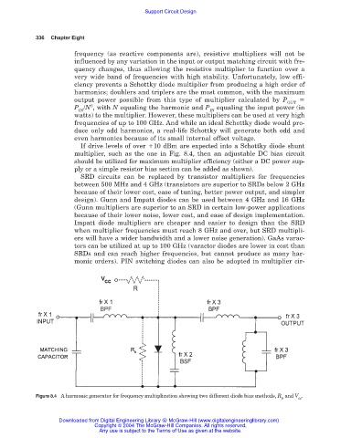
If drive levels of over 10 dBm are expected into a Schottky diode shunt
multiplier, such as the one in Fig. 8.4, then an adjustable DC bias circuit
should be utilized for maximum multiplier efficiency (either a DC power sup-
ply or a simple resistor bias section can be added as shown).
SRD circuits can be replaced by transistor multipliers for frequencies
between 500 MHz and 4 GHz (transistors are superior to SRDs below 2 GHz
because of their lower cost, ease of tuning, better power output, and simpler
design). Gunn and Impatt diodes can be used between 4 GHz and 16 GHz
(Gunn multipliers are superior to an SRD in certain low-power applications
because of their lower noise, lower cost, and ease of design implementation.
Impatt diode multipliers are cheaper and easier to design than the SRD
when multiplier frequencies must reach 8 GHz and over, but SRD multipli-
ers will have a wider bandwidth and a lower noise generation). GaAs varac-
tors can be utilized at up to 100 GHz (varactor diodes are lower in cost than
SRDs and can reach higher frequencies, but cannot produce as many har-
monic orders). PIN switching diodes can also be adopted in multiplier cir-
Figure 8.4 A harmonic generator for frequency multiplication showing two different diode bias methods, R and V .
b cc
Downloaded from Digital Engineering Library @ McGraw-Hill (www.digitalengineeringlibrary.com)
Copyright © 2004 The McGraw-Hill Companies. All rights reserved.
Any use is subject to the Terms of Use as given at the website.