
Page 359 - Complete Wireless Design
P. 359
Support Circuit Design
358 Chapter Eight
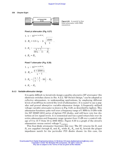
Figure 8.26 A coaxial in-line
fixed attenuator with SMA
connectors.
Fixed pi attenuator (Fig. 8.27)
1.
10 Loss (in dB)/10 .
2500
2. R 0.5 (
1) .
3
1
3. R .
1
1 1
50(
1) R
3
4. R R .
2 1
Fixed T attenuator (Fig. 8.28)
1.
10 Loss (in dB)/10 .
2 2500
2. R .
3
1
1
3. R 50 R .
2
1 3
4. R R .
1 2
8.4.3 Variable-attenuator design
It is quite difficult to iteratively design a quality absorptive RF attenuator (the
electronic switches shown in Sec. 8.2.2, “RF Switch Design,” can be adopted as
reflective attenuators, in undemanding applications, by employing different
levels of on/off bias to control the level of attenuation). It is easier to use a pop-
ular and proved absorptive variable-attenuator design. A frequently utilized
voltage-variable attenuator is shown in Fig. 8.29, as described by Agilent. This
attenuator functions quite well over a frequency range of 1 MHz to 3 GHz with
the HP HSMP-3810 series of Agilent PIN diodes, and will have very low dis-
tortion at low signal levels. It is economical and has a good return loss over its
entire attenuation and frequency range (greater than 11 dB over a control volt-
age of 0 to 15 V from 10 to 3000 MHz). Figure 8.30 is a graph of the circuit’s
attenuation versus control voltage V .
CONTROL
This four-diode attenuator functions this way: The DC returns for D and
2
D are supplied through R and R , while R , R , and R furnish the proper
3 1 2 3 4 6
impedance match for the particular PIN diodes chosen (in this case, the
Downloaded from Digital Engineering Library @ McGraw-Hill (www.digitalengineeringlibrary.com)
Copyright © 2004 The McGraw-Hill Companies. All rights reserved.
Any use is subject to the Terms of Use as given at the website.