Page 362 - Complete Wireless Design
P. 362

Support Circuit Design


                                                                          Support Circuit Design  361


                        Figure 8.31 (a) Balanced input; (b) Unbalanced input.


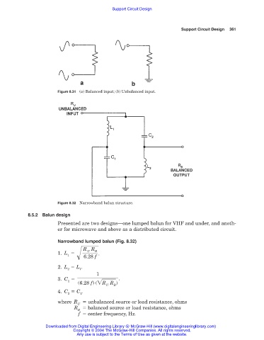
                        Figure 8.32 Narrowband balun structure.

            8.5.2 Balun design
                        Presented are two designs—one lumped balun for VHF and under, and anoth-
                        er for microwave and above as a distributed circuit.

                        Narrowband lumped balun (Fig. 8.32)
                                   R R
                                       B
                                    U
                        1. L             .
                            1      f
                                   6.28
                        2. L   L .
                            2    1
                                        1
                        3. C                     .
                            1
                                 (6.28 f) ( R R )
                                            U  B
                        4. C   C .
                            2    1
                        where R   unbalanced source or load resistance, ohms
                                U
                               R   balanced source or load resistance, ohms
                                B
                                 f   center frequency, Hz.
                   Downloaded from Digital Engineering Library @ McGraw-Hill (www.digitalengineeringlibrary.com)
                               Copyright © 2004 The McGraw-Hill Companies. All rights reserved.
                                Any use is subject to the Terms of Use as given at the website.
   357   358   359   360   361   362   363   364   365   366   367