
Page 358 - Complete Wireless Design
P. 358
Support Circuit Design
Support Circuit Design 357
In the early prototype stages of an AGC circuit it is a good idea to utilize
trimmers in place of certain critical fixed resistors in order to allow the values
of the AGC’s loop to be empirically optimized.
8.4 Attenuators
8.4.1 Introduction
Attenuators are either fixed or variable circuits to reduce signal amplitudes
and/or improve return loss, while maintaining the proper input and output
impedance (normally 50 ohms), of the stages they are attached to. Attenuators
are used extensively in wireless design.
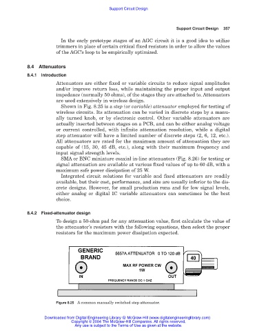
Shown in Fig. 8.25 is a step (or variable) attenuator employed for testing of
wireless circuits. Its attenuation can be varied in discrete steps by a manu-
ally turned knob, or by electronic control. Other variable attenuators are
actually inserted between stages on a PCB, and can be either analog voltage
or current controlled, with infinite attenuation resolution, while a digital
step attenuator will have a limited number of discrete steps (2, 6, 12, etc.).
All attenuators are rated for the maximum amount of attenuation they are
capable of (15, 30, 45 dB, etc.), along with their maximum frequency and
input signal strength levels.
SMA or BNC miniature coaxial in-line attenuators (Fig. 8.26) for testing or
signal attenuation are available at various fixed values of up to 60 dB, with a
maximum safe power dissipation of 25 W.
Integrated circuit solutions for variable and fixed attenuators are readily
available, but their cost, performance, and size are usually inferior to the dis-
crete designs. However, for small production runs and for low signal levels,
either analog or digital IC variable attenuators can sometimes be the best
choice.
8.4.2 Fixed-attenuator design
To design a 50-ohm pad for any attenuation value, first calculate the value of
the attenuator’s resistors with the following equations, then select the proper
resistors for the maximum power dissipation expected.
Figure 8.25 A common manually switched step attenuator.
Downloaded from Digital Engineering Library @ McGraw-Hill (www.digitalengineeringlibrary.com)
Copyright © 2004 The McGraw-Hill Companies. All rights reserved.
Any use is subject to the Terms of Use as given at the website.