
Page 361 - Complete Wireless Design
P. 361
Support Circuit Design
360 Chapter Eight
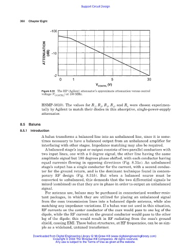
Figure 8.30 The HP (Agilent) attenuator’s approximate attenuation versus control
voltage (V ) at 100 MHz.
CONTRL
HSMP-3810). The values for R , R , R , R , and R were chosen experimen-
1 2 3 4 6
tally by Agilent to match their diodes in this absorptive, single-power-supply
attenuator.
8.5 Baluns
8.5.1 Introduction
A balun transforms a balanced line into an unbalanced line, since it is some-
times necessary to have a balanced output from an unbalanced amplifier for
interfacing with other stages. Impedance matching may also be required.
A balanced stage’s input or output consists of two parallel conductors with
two input lines, one with a 0 degree signal, the other line having the same
amplitude signal but 180 degrees phase shifted, with each conductor having
equal currents flowing in opposing directions (Fig. 8.31a). An unbalanced
stage’s output has a single conductor for the current, with a second conduc-
tor for the ground return, and is the dominant technique found in contem-
porary RF design (Fig. 8.31b). But when a balanced source must be
converted to unbalanced, this demands that the two differential signals be
mixed (combined) so that they are in phase in order to output an unbalanced
signal.
For antenna use, baluns may be purchased in connectorized weather-resis-
tant packages, in which they are utilized for placing an unbalanced signal
from the coax transmission lines into a balanced dipole antenna, while also
matching any impedance variations. If a balun was not used in this situation,
RF currents on the center conductor of the coax would pass to one leg of the
dipole, while the RF current on the ground conductor would pass to the other
leg of the dipole; this would result in RF radiating from the coax’s ground
shield, causing EMI. These balun structures, at HF frequencies, can be as sim-
ple as a wideband, untuned transformer.
Downloaded from Digital Engineering Library @ McGraw-Hill (www.digitalengineeringlibrary.com)
Copyright © 2004 The McGraw-Hill Companies. All rights reserved.
Any use is subject to the Terms of Use as given at the website.