
Page 357 - Complete Wireless Design
P. 357
Support Circuit Design
356 Chapter Eight
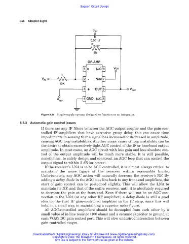
Figure 8.24 Single-supply op-amp designed to function as an integrator.
8.3.3 Automatic gain control issues
If there are any IF filters between the AGC output coupler and the gain-con-
trolled IF amplifiers that have excessive group delay, this can cause time
impediments in sensing that a signal has increased or decreased in amplitude,
causing AGC loop instabilities. Another major cause of loop instability can be
the desire to obtain excessively tight AGC control of the IF or baseband output
amplitude. In most cases, an AGC circuit with less gain and less absolute con-
trol of the output amplitude will be much more stable. It is still possible,
nonetheless, to safely design and construct an AGC loop that can control the
output signal to within 2 dB (or better).
If the receiver’s LNA is to be AGC controlled, it is almost always critical to
maintain the noise figure of the receiver within reasonable limits.
Unfortunately, any AGC action will naturally decrease the receiver’s NF. By
adding a delay diode in the AGC bias line back to any front-end amplifiers, the
start of gain control can be postponed slightly. This will allow the LNA to
maintain its NF, and that of the entire receiver, until it is absolutely required
to decrease the gain at the front end. Even if there will not be an AGC con-
nection to the LNA (or any other RF amplifier), a delay diode is still a good
idea for the first IF gain-controlled amplifier in the IF strip, since this will
help, in a small way, in maintaining a superior noise figure.
All AGC-controlled amplifiers should be decoupled from each other by a
small value of in-line resistor (100 ohms) and a ceramic capacitor to ground at
each VGA’s DC gain control port. This will slow undesired interaction between
gain-controlled stages.
Downloaded from Digital Engineering Library @ McGraw-Hill (www.digitalengineeringlibrary.com)
Copyright © 2004 The McGraw-Hill Companies. All rights reserved.
Any use is subject to the Terms of Use as given at the website.