
Page 115 - Compression Machinery for Oil and Gas
P. 115
102 SECTION II Types of Equipment
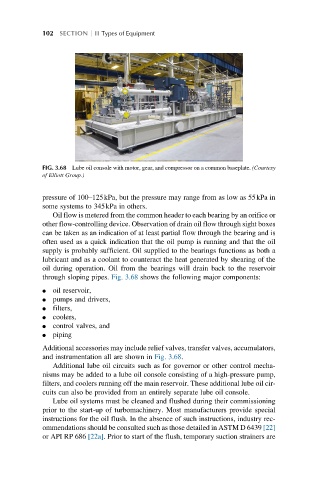
FIG. 3.68 Lube oil console with motor, gear, and compressor on a common baseplate. (Courtesy
of Elliott Group.)
pressure of 100–125kPa, but the pressure may range from as low as 55kPa in
some systems to 345kPa in others.
Oil flow is metered from the common header to each bearing by an orifice or
other flow-controlling device. Observation of drain oil flow through sight boxes
can be taken as an indication of at least partial flow through the bearing and is
often used as a quick indication that the oil pump is running and that the oil
supply is probably sufficient. Oil supplied to the bearings functions as both a
lubricant and as a coolant to counteract the heat generated by shearing of the
oil during operation. Oil from the bearings will drain back to the reservoir
through sloping pipes. Fig. 3.68 shows the following major components:
l oil reservoir,
l pumps and drivers,
l filters,
l coolers,
l control valves, and
l piping
Additional accessories may include relief valves, transfer valves, accumulators,
and instrumentation all are shown in Fig. 3.68.
Additional lube oil circuits such as for governor or other control mecha-
nisms may be added to a lube oil console consisting of a high-pressure pump,
filters, and coolers running off the main reservoir. These additional lube oil cir-
cuits can also be provided from an entirely separate lube oil console.
Lube oil systems must be cleaned and flushed during their commissioning
prior to the start-up of turbomachinery. Most manufacturers provide special
instructions for the oil flush. In the absence of such instructions, industry rec-
ommendations should be consulted such as those detailed in ASTM D 6439 [22]
or API RP 686 [22a]. Prior to start of the flush, temporary suction strainers are