
Page 277 - Compression Machinery for Oil and Gas
P. 277
262 SECTION II Types of Equipment
1
A
8
11
9
12
10
B
4 2 4 5 5 7
14
6
5 5
3
13
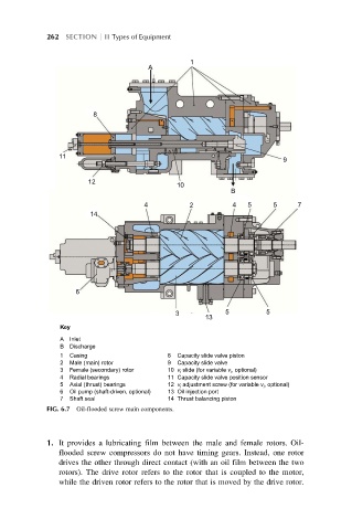
Key
A Inlet
B Discharge
1 Casing 8 Capacity slide valve piston
2 Male (main) rotor 9 Capacity slide valve
3 Female (secondary) rotor 10 v i slide (for variable v i , optional)
4 Radial bearings 11 Capacity slide valve position sensor
5 Axial (thrust) bearings 12 v i adjustment screw (for variable v i , optional)
6 Oil pump (shaft-driven, optional) 13 Oil injection port
7 Shaft seal 14 Thrust balancing piston
FIG. 6.7 Oil-flooded screw main components.
1. It provides a lubricating film between the male and female rotors. Oil-
flooded screw compressors do not have timing gears. Instead, one rotor
drives the other through direct contact (with an oil film between the two
rotors). The drive rotor refers to the rotor that is coupled to the motor,
while the driven rotor refers to the rotor that is moved by the drive rotor.