
Page 282 - Compression Machinery for Oil and Gas
P. 282
Screw Compressors Chapter 6 267
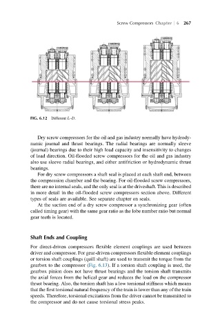
FIG. 6.12 Different L–D.
Dry screw compressors for the oil and gas industry normally have hydrody-
namic journal and thrust bearings. The radial bearings are normally sleeve
(journal) bearings due to their high load capacity and insensitivity to changes
of load direction. Oil-flooded screw compressors for the oil and gas industry
also use sleeve radial bearings, and either antifriction or hydrodynamic thrust
bearings.
For dry screw compressors a shaft seal is placed at each shaft end, between
the compression chamber and the bearing. For oil-flooded screw compressors,
there are no internal seals, and the only seal is at the driveshaft. This is described
in more detail in the oil-flooded screw compressors section above. Different
types of seals are available. See separate chapter on seals.
At the suction end of a dry screw compressor a synchronizing gear (often
called timing gear) with the same gear ratio as the lobe number ratio but normal
gear teeth is located.
Shaft Ends and Coupling
For direct-driven compressors flexible element couplings are used between
driver and compressor. For gear-driven compressors flexible element couplings
or torsion shaft couplings (quill shaft) are used to transmit the torque from the
gearbox to the compressor (Fig. 6.13). If a torsion shaft coupling is used, the
gearbox pinion does not have thrust bearings and the torsion shaft transmits
the axial forces from the helical gear and reduces the load on the compressor
thrust bearing. Also, the torsion shaft has a low torsional stiffness which means
that the first torsional natural frequency of the train is lower than any of the train
speeds. Therefore, torsional excitations from the driver cannot be transmitted to
the compressor and do not cause torsional stress peaks.