
Page 280 - Compression Machinery for Oil and Gas
P. 280
Screw Compressors Chapter 6 265
Design Features
In large screw compressors the casing is normally split horizontally (axially) for
ease of maintenance (see Fig. 6.6). For oil-injected screw compressors or for
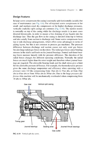
small- and medium-sized dry compressors or for higher discharge pressures,
vertically (radially) split casings are common (Fig. 6.10). The suction nozzle
is normally on top of the casing while the discharge nozzle is in most cases
directed downwards, in order to ensure a free draining of any liquids into the
discharge line. Thus the gas flow in the casing is directed from top to bottom
and also axially from suction to discharge end. Some screw compressors have
top or side discharge arrangements, which offers some advantages in terms of
piping layout, but this is not common in process gas machines. The pressure
difference between discharge and suction causes not only axial gas forces
but also large radial gas forces on the rotors. The radial gas forces cause bending
stresses in the shafts and loads on the journal bearings. Journal and thrust bear-
ing forces increase linearly with the pressure difference. The direction of the
radial forces changes for different operating conditions. Normally the radial
forces are much higher than the rotor weight and therefore robust journal bear-
ings are required. The allowable bearing loads and the shaft stress give a limit
for the allowable pressure difference. For example, the thermodynamic process
gives the same discharge temperature and efficiency when operating with a
pressure ratio 3.0 like compressing from 1bar abs to 3bar abs, or from 2bar
abs to 6bar abs or from 10bar abs to 30bar abs. Due to the large pressure dif-
ference this machine will be mechanically overloaded when compressing from
10 abs to 30bar abs.
FIG. 6.10 Vertical split dry screw.