
Page 281 - Compression Machinery for Oil and Gas
P. 281
266 SECTION II Types of Equipment
Rotor Design
The rotor design is defined by the shape and number of lobes on the rotors
and the rotor length indicated by the L/D ratio. For a given rotor diameter the
geometrical volume flow increases proportional with the rotor length. It
should be noted that the achievable pressure ratio is independent of the
L/D; however, the allowable pressure difference is inversely proportional
to L/D. The rotor design is carefully chosen with respect to the intended
applications. Any design is a compromise between the conflicting require-
ments of a large volume flow for a given machine size and high rotor bend-
ing stiffness.
Compressors for high flow and low-pressure difference have long rotors
with few lobes. These are normally dry screw compressors. Lobe combina-
tions may be three lobes on the male rotor and four or five lobes on the
female rotor (3/4 or 3/5). L/D is >1.8 up to approximately 2.2. Due to the
long and slender rotor these machines are only suitable for low-pressure
differences.
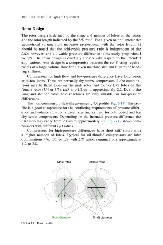
The most common profile is the asymmetric 4/6 profile (Fig. 6.11). This pro-
file is a good compromise for the conflicting requirements of pressure differ-
ence and volume flow for a given size and is used for oil-flooded and for
dry screw compressors. Depending on the intended pressure difference the
L/D ratio may range from <1 up to approximately 2.2. Fig. 6.12 shows com-
pressors with different L/D ratios.
Compressors for high-pressure differences have short stiff rotors with
a higher number of lobes. Typical for oil-flooded compressors are lobe
combinations 4/6, 5/6, or 5/7 with L/D ratios ranging from approximately
1.2to2.8.
Male rotor Female rotor
Root diameter Shaft diameter
FIG. 6.11 Rotor profile.