
Page 278 - Compression Machinery for Oil and Gas
P. 278
Screw Compressors Chapter 6 263
A
1
6
5
11
4
9
10
B
8
7
3
2
4
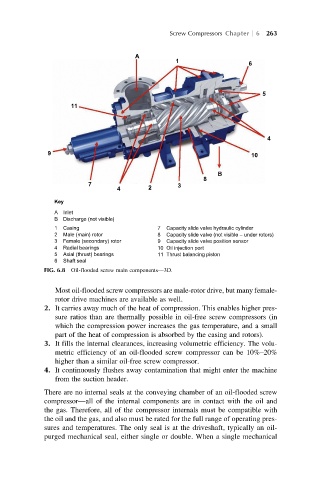
Key
A Inlet
B Discharge (not visible)
1 Casing 7 Capacity slide valve hydraulic cylinder
2 Male (main) rotor 8 Capacity slide valve (not visible – under rotors)
3 Female (secondary) rotor 9 Capacity slide valve position sensor
4 Radial bearings 10 Oil injection port
5 Axial (thrust) bearings 11 Thrust balancing piston
6 Shaft seal
FIG. 6.8 Oil-flooded screw main components—3D.
Most oil-flooded screw compressors are male-rotor drive, but many female-
rotor drive machines are available as well.
2. It carries away much of the heat of compression. This enables higher pres-
sure ratios than are thermally possible in oil-free screw compressors (in
which the compression power increases the gas temperature, and a small
part of the heat of compression is absorbed by the casing and rotors).
3. It fills the internal clearances, increasing volumetric efficiency. The volu-
metric efficiency of an oil-flooded screw compressor can be 10%–20%
higher than a similar oil-free screw compressor.
4. It continuously flushes away contamination that might enter the machine
from the suction header.
There are no internal seals at the conveying chamber of an oil-flooded screw
compressor—all of the internal components are in contact with the oil and
the gas. Therefore, all of the compressor internals must be compatible with
the oil and the gas, and also must be rated for the full range of operating pres-
sures and temperatures. The only seal is at the driveshaft, typically an oil-
purged mechanical seal, either single or double. When a single mechanical