
Page 279 - Compression Machinery for Oil and Gas
P. 279
264 SECTION II Types of Equipment
seal is used, the seal is usually fed by the common oil system. When higher
safety requirements call for a double mechanical seal, it is typical for a sep-
arate oil system to be used for the driveshaft seal. This allows better control
of the temperature, pressure, and flow of the oil to the seal, and also ensures
that any oil leakage on the atmospheric side of the seal does not contain any
process gas.
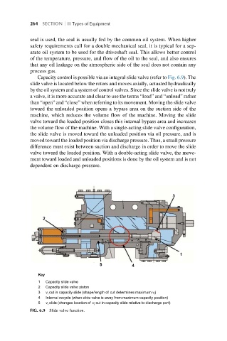
Capacity control is possible via an integral slide valve (refer to Fig. 6.9). The
slide valve is located below the rotors and moves axially, actuated hydraulically
by the oil system and a system of control valves. Since the slide valve is not truly
a valve, it is more accurate and clear to use the terms “load” and “unload” rather
than “open” and “close” when referring to its movement. Moving the slide valve
toward the unloaded position opens a bypass area on the suction side of the
machine, which reduces the volume flow of the machine. Moving the slide
valve toward the loaded position closes this internal bypass area and increases
the volume flow of the machine. With a single-acting slide valve configuration,
the slide valve is moved toward the unloaded position via oil pressure, and is
moved toward the loaded position via discharge pressure. Thus, a small pressure
difference must exist between suction and discharge in order to move the slide
valve toward the loaded position. With a double-acting slide valve, the move-
ment toward loaded and unloaded positions is done by the oil system and is not
dependent on discharge pressure.
3
2
1
5
4
Key
1 Capacity slide valve
2 Capacity slide valve piston
3 v i cut in capacity slide (shape/length of cut determines maximum v i )
4 Internal recycle (when slide valve is away from maximum capacity position)
5 v i slide (changes location of v i cut in capacity slide relative to discharge port)
FIG. 6.9 Slide valve function.