
Page 18 - Computational Fluid Dynamics for Engineers
P. 18
1.1 Skin-Friction Drag Reduction 3
to the wall boundary conditions including variations of longitudinal and trans-
verse surface curvatures, the nature of the surface and heat and mass transfer
through the surface. A partial exception is the use of thin airfoils (LEBUs) in
the outer region of the boundary layer to break up the large eddy structure of
turbulent flow [1].
In this section the discussion is limited to laminar flow control (LFC) and
the reader is referred to [1] for a discussion of other techniques for reducing
the skin-friction drag. In subsection 1.1.1, a brief description of laminar flow
control first by "Adjustment of Pressure Gradient by Shaping," then by "Suction
Through Slotted or Perforated Surfaces" is given. This subsection is followed by
a description and application of a calculation method to natural laminar flow
(NLF) and hybrid laminar flow control (HLFC) wings (Subsection 1.1.2).
1.1.1 Laminar Flow Control
Adjustment of Pressure Gradient by Shaping
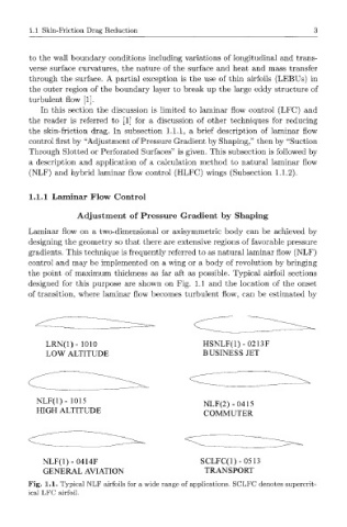
Laminar flow on a two-dimensional or axisymmetric body can be achieved by
designing the geometry so that there are extensive regions of favorable pressure
gradients. This technique is frequently referred to as natural laminar flow (NLF)
control and may be implemented on a wing or a body of revolution by bringing
the point of maximum thickness as far aft as possible. Typical airfoil sections
designed for this purpose are shown on Fig. 1.1 and the location of the onset
of transition, where laminar flow becomes turbulent flow, can be estimated by
LRN(l)- 1010 HSNLF(1)-0213F
LOW ALTITUDE BUSINESS JET
NLF(l)- 1015
NLF(2)-0415
HIGH ALTITUDE
COMMUTER
NLF(1)-0414F SCLFC(1)-0513
GENERAL AVIATION TRANSPORT
Fig. 1.1. Typical NLF airfoils for a wide range of applications. SCLFC denotes supercrit-
ical LFC airfoil.