
Page 19 - Computational Fluid Dynamics for Engineers
P. 19
4 1. Introduction
n
using the e -method discussed in Chapter 8. The success of this technique and
of the calculation method also depends on factors besides the pressure gradient
including surface roughness, surface waviness, freestream turbulence, and the
concentration of a second phase such as rain or solid particles in water, all of
which can play a role in triggering transition [2]. The influence of these factors
can usually be avoided by careful design, for example by keeping the surface
waviness and roughness below the allowable limits.
A number of modern low-speed aircraft make use of extended regions of nat-
ural laminar flow on their wings [1] but transonic cruise, and the swept wings
required for this configuration, introduce further complications. In particular,
flow from the fuselage boundary layer can introduce instabilities which result
in turbulent flow along the attachment line of the wing [2], or a favorable pres-
sure gradient on the upper surface can result in a shock wave which interacts
with the boundary-layer to cause turbulent flow. The first problem depends on
the Reynolds number, sweep angle and curvature of the leading edge and it
is possible to shape the leading edge of the wing so that the attachment-line
flow is laminar. In this case it is likely that, depending on the sweep angle, the
flow may become turbulent away from the attachment line due to the crossflow
instability discussed in [2]. In subsection 1.1.2 calculations are presented for a
typical NLF wing in incompressible flow to demonstrate the role of sweep angle
and crossflow on transition.
Extending the region of natural laminar flow on fuselages in order to reduce
the fuselage drag is also important, as indicated by the examples of Fig. 1.2,
relevant to transport aircraft [1]. It should be pointed out that the total skin-
friction drag of a modern wide-body transport aircraft is about 40% of the
total airplane drag, with approximately 3% from nacelles and pylons, 15% from
fuselage, 15% from wing, and 8% from empennage. Thus, nacelles and pylons
account for about 8% of the total skin-friction drag, while the fuselage, wing and
empennage account for 38%, 35% and 20%, respectively. For smaller airplanes,
such as the MD-80 and 737, the portion of the total skin-friction drag is usually
higher than for wide bodies.
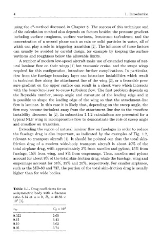
Table 1.1. Drag coefficients for an
axisymmetric body with a fineness
ratio 6.14 at a = 0, R L = 40.86 x
10 6 [1].
XtT C d x 10 2
0.322 2.60
0.15 3.43
0.10 3.62
0.05 3.74