
Page 23 - Computational Fluid Dynamics for Engineers
P. 23
1. Introduction
n
0.3 0.4 0.2 0.3
x/c x/c
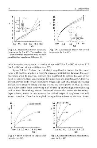
Fig. 1.5. Amplification factors for several Fig. 1.6. Amplification factors for several
frequencies for A — 20°. The numbers 1 to frequencies for A = 40°.
7 show different frequencies used for each
amplification calculation (Chapter 8).
with increasing sweep angle, occurring at x/c = 0.22 for A = 30°, at x/c = 0.12
for A = 35° and at x/c = 0.05 at A = 50°.
Figures 1.7 to 1.9 show the calculated amplification factors for the same
wing with suction, which is a powerful means of maintaining laminar flow over
the whole wing. In practice, however, this is difficult to achieve because of the
need for ailerons, flaps and openings for inspection and maintenance. Clearly a
suction system adds to the complexity, weight and cost of a design. Increasing
suction rates requires larger ducting system and more power so that at some
point all available space in the wing may be used up and the higher suction drag
will produce diminishing returns. Increased suction also makes the boundary-
layer thinner, which in turn reduces the critical height of roughness that will
cause transition. If suction is applied through discrete holes or slots and is not
10 / NO SUCTION 10 -NO SUCTION
9 9
n 8 !" n 8
7 7 S ?
6 - ^^~ S 4 6 / / s i / ^
5 - 5 - /
4 - 4 -/
3 - / -— SI 3 r~ S 2 /
2 7 2
1 1
0 ^_i___ 1 1 1 1 1 0 i i i i i i
0.0 0.1 0.2 0.3 0.4 0.5 0.6 0.0 0.1 0.2 0.3 0.4 0.5 0.6
x/c x/c
Fig. 1.7. Effect of suction on amplification Fig. 1.8. Effect of suction on amplification
rates for A = 30°. rates for A = 40°.