
Page 27 - Computational Fluid Dynamics for Engineers
P. 27
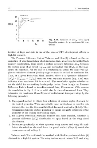
12                                                          1.  Introduction


                   MACH=0.15
               15
                  -
                    /vTo.2/^^
               12           ^0.25
         |AC P
                9  -
                6
                3
                  -
                0     1    !   I    I   I
                 0    4   8   12   16  20    Fig.  1.11.  Variation  of  |Z\C P |  with  chord
                                             Reynolds  number  R c  at  maximum  lift  con-
                                 Re          ditions.


         location  of  flaps  and  slats  is  one  of  the  aims  of  CFD  development  efforts  in
         high-lift  research.
            The  Pressure  Difference  Rule  of  Valarezo  and  Chin  [6]  is  based  on  the  ex-
         amination  of wind  tunnel  data  which  indicates that,  at  a  given  Reynolds/Mach
         number  combination,  there  exists  a  certain  pressure  difference  AC V  between
         the  suction  peak  of  an  airfoil  (Cp) min  and  its  trailing  edge  (C p)te  a  t  the  max-
         imum  lift  condition.  For  the  case  of  a  multielement  airfoil,  the  same  rule  ap-
         plies  to  whichever  element  (leading-edge  or  main)  is  critical  at  maximum  lift.
         Thus,  at  a  given  freestream  Mach  number,  there  is  a  "pressure  difference"
                 l(C P)    (Cp)te|  variation  with  Reynolds  number  (Fig.  1.11)  that
         \AC n
         indicates  when  maximum  lift  is  attained.  This  correlation  applies  whether  or
         not  the  airfoil  has  an  auxiliary  leading-edge  device.  Even  though  the  Pressure
         Difference  Rule  is  based  on  two-dimensional  data,  Valarezo  and  Chin  assume
        the  correlation  in  Fig.  1.11  to  be  valid  also  for  three-dimensional  flows.  They
         determine  the  maximum  lift  coefficient  of  multielement  transport  wings  by  the
         following  procedure:
          1.  Use  a  panel  method  to  obtain  flow  solutions  at  various  angles  of attack  for
            the  desired  geometry.  While  any  reliable  panel  method  can  be  used  for  this
            purpose, they  use the  Hess panel method  discussed  in detail  in  [4, 5, 7]. They
            recommend  sufficient  surface  paneling  to  ensure  adequate  definition  of  the
            geometry  at  the  leading  and  trailing  edges.
         2.  For  a  given  freestream  Reynolds  number  and  Mach  number,  construct  a
            pressure  difference  \AC P\  distribution  vs.  span  based  on  the  wing  chord
            distribution.
         3.  Determine  graphically  at  what  spanwise  wing  station  and  wing  lift  coef-
            ficient  the  solutions  obtained  from  the  panel  method  (Step  1)  match  the
            curve  constructed  in  Step  2.

            Valarezo  and  Chin  validated  this  method  with  RAE  experimental  data  [8]
         obtained  for  a  high-lift  system.  The  wing  had  an  aspect  ratio  of  8.35  and  wing