
Page 25 - Computational Fluid Dynamics for Engineers
P. 25
10 1. Introduction
N
0 r u su U 1 KJ1N c q
9
8 - ,
7 S 2
6 _ 1 / / /
5
4 / S3 /
3
2
1
0 / | ^S
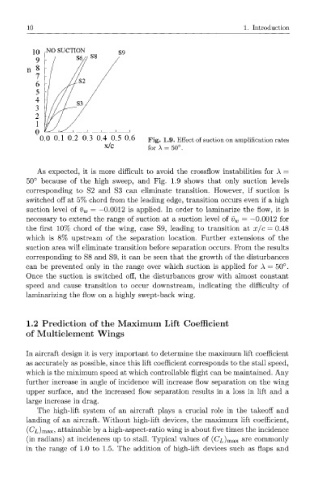
0 0 0.1 0.2 0.3 0.4 0.5 0.6 Fig. 1.9. Effect of suction on amplification rates
x/c for A = 50°.
As expected, it is more difficult to avoid the crossflow instabilities for A =
50° because of the high sweep, and Fig. 1.9 shows that only suction levels
corresponding to S2 and S3 can eliminate transition. However, if suction is
switched off at 5% chord from the leading edge, transition occurs even if a high
suction level of v w = —0.0012 is applied. In order to laminarize the flow, it is
necessary to extend the range of suction at a suction level of v w = —0.0012 for
the first 10% chord of the wing, case S9, leading to transition at x/c — 0.48
which is 8% upstream of the separation location. Further extensions of the
suction area will eliminate transition before separation occurs. From the results
corresponding to S8 and S9, it can be seen that the growth of the disturbances
can be prevented only in the range over which suction is applied for A = 50°.
Once the suction is switched off, the disturbances grow with almost constant
speed and cause transition to occur downstream, indicating the difficulty of
laminarizing the flow on a highly swept-back wing.
1.2 Prediction of he Maximum Lift Coefficient
t
of Multielement Wings
In aircraft design it is very important to determine the maximum lift coefficient
as accurately as possible, since this lift coefficient corresponds to the stall speed,
which is the minimum speed at which controllable flight can be maintained. Any
further increase in angle of incidence will increase flow separation on the wing
upper surface, and the increased flow separation results in a loss in lift and a
large increase in drag.
The high-lift system of an aircraft plays a crucial role in the takeoff and
landing of an aircraft. Without high-lift devices, the maximum lift coefficient,
(Czjmax? attainable by a high-aspect-ratio wing is about five times the incidence
(in radians) at incidences up to stall. Typical values of (C^Jmax are commonly
in the range of 1.0 to 1.5. The addition of high-lift devices such as flaps and