
Page 22 - Computational Fluid Dynamics for Engineers
P. 22
1.1 Skin-Friction Drag Reduction 7
1.2
1.0
WU«
0.8
0.6
0.4
0.2
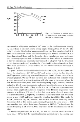
0.0 Fig. 1.4. Variation of inviscid veloc-
0.0 0.2 0.4 0.6 0.8 1.0 ity distribution with sweep angle for
x/c the NACA 65-412 wing.
7
correspond to a Reynolds number of 10 , based on the total freest ream velocity
Voc and chord c, and for several sweep angles ranging from 0° to 50°. The
inviscid velocity distribution was computed from the Hess panel method [4, 5]
which is an extension of the two-dimensional panel method of Section 6.4 to
three-dimensional flows and the boundary-layer calculations were performed
by a boundary-layer method for three-dimensional flows which is an extension
of the two-dimensional boundary-layer method of Chapter 7 [2,4]. Transition
n
calculations are performed by using the e -method for three-dimensional flows
n
which is an extension of the e -method for two-dimensional flows discussed in
Chapter 8 [2,3].
Figure 1.4 shows the inviscid velocity distribution Ue/u^ for the upper sur-
face of the wing for A = 20°, 30° and 40° and, as can be seen, the flow has a fa-
vorable pressure gradient up to around 50-percent chord, followed by an adverse
pressure gradient. We expect that the cross-flow instability will be rather weak
at lower sweep angles, so that transition will take place in the region where the
flow deceleration takes place. With increasing sweep angle, however, crossflow
instability [2] will begin to dominate and cause transition to occur in the region
of acceleration. The results of Fig. 1.5 for A = 20° confirm this expectation and
indicate that amplification factors computed with different frequencies reach
values of n as high as 6.75 at x/c = 0.44 but not a value of n = 8 as required
to indicate transition (Chapter 8). Additional calculations show that transition
occurs at x/c = 0.65 and is not caused by crossflow instability. The results for
A = 40°, shown in Fig. 1.6, however, indicate that crossflow instability makes
its presence felt at this sweep angle, causing transition to occur at x/c = 0.08
corresponding to a radian disturbance frequency of 0.03740. The location of the
critical frequency is at x/c = 0.0046, very close to the attachment line of the
wing.
Calculations performed for A = 30°, 35° and 50° indicate results similar to
those for A = 40° in that the transition location moves closer to the leading edge