
Page 20 - Computational Fluid Dynamics for Engineers
P. 20
1.1 Skin-Friction Drag Reduction 5
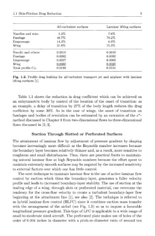
All-turbulent surfaces Laminar lifting surfaces
Nacelles and misc. 5.2% 7.6%
Fuselage 48.7% 70.2%
Empennage 14.3% 6.9%
Wing 31.8% 15.3%
Nacelle and others 0.0010 0.0010
Fuselage 0.0092 0.0092
Empennage 0.0027 0.0009
Wing 0.0060 0.0020
Total profile CD 0.0189 0.0131
Fig. 1.2. Profile drag buildup for all-turbulent transport jet and airplane with laminar
lifting surfaces [1].
Table 1.1 shows the reduction in drag coefficient which can be achieved on
an axisymmetric body by control of the location of the onset of transition: as
an example, a delay of transition by 27% of the body length reduces the drag
coefficient by some 30%. As in the case of wings, the onset of transition on
n
fuselages and bodies of revolution can be estimated by an extension of the e -
method discussed in Chapter 8 from two-dimensional flows to three-dimensional
flows discussed in [2,3].
Suction Through Slotted or Perforated Surfaces
The attainment of laminar flow by adjustment of pressure gradient by shaping
becomes increasingly more difficult as the Reynolds number increases because
the boundary layer becomes relatively thinner and, as a result, more sensitive to
roughness and small disturbances. Thus, there are practical limits to maintain-
ing natural laminar flow at high Reynolds numbers because the effort spent to
maintain extremely smooth surfaces may be negated by the increased sensitivity
to external factors over which one has little control.
The next technique to maintain laminar flow is the use of active laminar flow
control by suction which thins the boundary-layer, generates a fuller velocity
profile and leads to increased boundary-layer stability. The use of suction at the
leading edge of a wing, through slots or perforated material, can overcome the
tendency for the cross-flow velocity to create a turbulent boundary-layer flow
beginning at the attachment line [1], see also [2]. The technique is referred to
as hybrid laminar-flow control (HLFC) since it combines suction mass transfer
with the arrangement of the airfoil (see Fig. 1.3) so as to impose a favorable
longitudinal pressure gradient. This type of LFC is applicable to a wide range of
small to moderate sized aircraft. The perforated plate makes use of holes of the
order of 0.004 inches in diameter with a pitch-to-diameter ratio of around ten