
Page 21 - Computational Fluid Dynamics for Engineers
P. 21
6 1. Introduction
- SUCTION
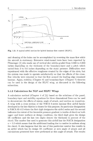
Fig. 1.3. A typical airfoil section for hybrid laminar flow control (HLFC).
and cleaning of the holes can be accomplished by reversing the mass flow while
the aircraft is stationary. Extensive wind-tunnel tests have been reported by
Pfenninger [1] who made use of vertical slot widths graded from 0.008 to 0.003
inches depending on the thickness of the boundary-layer and a pitch which
varied from 3 to 0.6 inches depending on the static pressure. Difficulties were
experienced with the effective roughness created by the edges of the slots, but
the system was made to operate satisfactorily so that the effects of the cross-
flow velocity were removed in that the flow around the leading edge remained
laminar. Again, stability (Chapter 8) and boundary-layer (Chapter 7) theories
can be used in the design of the HLFC wing, as discussed in the following
subsection.
1.1.2 Calculations for NLF and HLFC Wings
A calculation method (Chapter 4 of [1]) based on the solutions of the panel,
boundary-layer and stability equations for three dimensional flows can be used
to demonstrate the effects of sweep, angle of attack, and suction on transition.
A wing with a cross section of the NACA 6-series laminar flow airfoil family
developed in the late thirties is chosen for this purpose. Its particular designation
is NACA 65-412 where the first digit designates the airfoil series and the second
indicates the extent of the favorable pressure gradient in tenths of chord on both
upper and lower surfaces at design condition; the third digit gives the design
lift coefficient and the last two digits denote the thickness in percent of the
chord. The camber line used to generate this airfoil has the NACA designation
a = 1.0 which means that the additional loading due to camber is uniform along
the chord. It also happens that the use of this particular camber line results in
an airfoil which has its design lift coefficient at zero angle of attack and all
calculations presented here were performed at this angle of attack. The results