
Page 32 - Computational Fluid Dynamics for Engineers
P. 32
1.2 Prediction of the Maximum Lift Coefficient of Multielement Wings 17
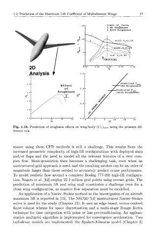
Limit AC Curve
1 No Roughness
2 With Roughness
a=12° C =1.19
2D
Analysis
Predicted C LMAX
(No Roughness)
Predicted C LMAX
(with Roughness)
a a
(
Fig. 1.18. Prediction of roughness effects on wing-body CL) max using the pressure dif-
ference rule.
mance using these CFD methods is still a challenge. This results from the
increased geometric complexity of high-lift configurations with deployed slats
and/or flaps and the need to model all the relevant features of a very com-
plex flow. Mesh-generation then becomes a challenging task, even when an
unstructured-grid approach is used, and the resulting meshes can be an order of
magnitude larger than those needed to accurately predict cruise performance.
To model realistic flow around a complete Boeing 777-200 high-lift configura-
tion, Rogers et al. [12] employ 22.4 million grid points using overset grids. The
prediction of maximum lift and wing stall constitutes a challenge even for a
clean wing configuration, as massive flow separation must be modelled.
An application of a Navier-Stokes method to the investigation of an aircraft
maximum lift is reported in [13]. The NSU3D [14] unstructured Navier-Stokes
solver is used for the study (Chapter 12). It uses an edge-based, vertex-centred
finite-volume scheme for space discretisation and a multi-stage Runge-Kutta
technique for time integration with point or line pre-conditioning. An agglom-
eration multigrid algorithm is implemented for convergence acceleration. Two
turbulence models are implemented: the Spalart-Allmaras model (Chapter 3)