
Page 36 - Computational Fluid Dynamics for Engineers
P. 36
1.3 Aircraft Design and Power Plant Integration 21
LTL 1INUK ItAI . UK II S „ .
(a) (b)
Fig. 1.21. (a) KTRAN rectangular mesh, (b) KTRAN solutions at three stages of Global
Express fuselage design (B165, B170, B179), Mach 0.85.
(a) (b)
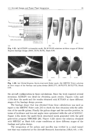
Fig. 1.22. (a) Global Express block-structured Euler mesh, (b) MBTEC Euler solution
at three stages of the fuselage and pylon design (B165/P71, B170/P73, B172/P73), Mach
0.85.
the aircraft configuration in these calculations. Since the work required several
iterations, KTRAN was ideal for obtaining quick results. Figures 1.21a and
1.21b show the mesh and the results obtained with KTRAN at three different
stages of the fuselage design process.
The fuselage shape that was obtained from these calculations was used as
input to the MBTEC Euler code [19] to check the flow situation with the addi-
tion of the nacelle pylons. Finally the pylons shape and the nacelles position, in
terms of incidence and toe-out angles were optimized with the aid of MBTEC.
Figure 1.22a shows the multi-block structured mesh generated with the grid
generation program MBGRID [20]. Figure 1.22b shows the solution obtained
with MBTEC at Mach 0.85 cruise conditions at three different stages of the
fuselage and pylon design.
The integration of the pylons and nacelles was verified in a wind tunnel
test that was conducted at the Aircraft Research Association (ARA) 8 ft. x 9 ft.