
Page 34 - Computational Fluid Dynamics for Engineers
P. 34
1.3 Aircraft Design and Power Plant Integration 19
CL-601 WBN
B82 W50 F5 N51 P54
(a)
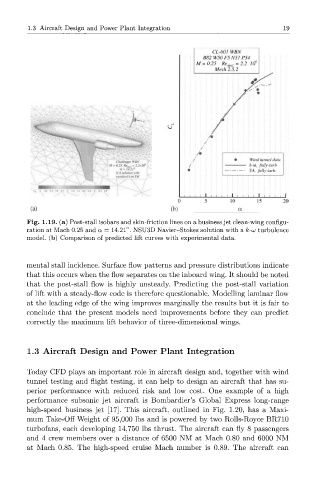
Fig. 1.19. (a) Post-stall isobars and skin-friction lines on a business jet clean-wing configu-
ration at Mach 0.25 and a — 14.21°. NSU3D Navier-Stokes solution with a k-uj turbulence
model, (b) Comparison of predicted lift curves with experimental data.
mental stall incidence. Surface flow patterns and pressure distributions indicate
that this occurs when the flow separates on the inboard wing. It should be noted
that the post-stall flow is highly unsteady. Predicting the post-stall variation
of lift with a steady-flow code is therefore questionable. Modelling laminar flow
at the leading edge of the wing improves marginally the results but it is fair to
conclude that the present models need improvements before they can predict
correctly the maximum lift behavior of three-dimensional wings.
1.3 Aircraft Design and Power Plant Integration
Today CFD plays an important role in aircraft design and, together with wind
tunnel testing and flight testing, it can help to design an aircraft that has su-
perior performance with reduced risk and low cost. One example of a high
performance subsonic jet aircraft is Bombardier's Global Express long-range
high-speed business jet [17]. This aircraft, outlined in Fig. 1.20, has a Maxi-
mum Take-Off Weight of 95,000 lbs and is powered by two Rolls-Royce BR710
turbofans, each developing 14,750 lbs thrust. The aircraft can fly 8 passengers
and 4 crew members over a distance of 6500 NM at Mach 0.80 and 6000 NM
at Mach 0.85. The high-speed cruise Mach number is 0.89. The aircraft can