
Page 35 - Computational Fluid Dynamics for Engineers
P. 35
20 1. Introduction
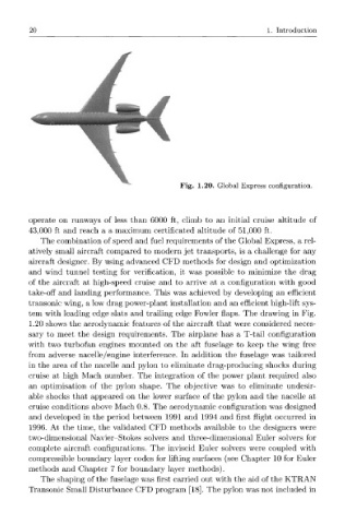
Fig. 1.20. Global Express configuration.
operate on runways of less than 6000 ft, climb to an initial cruise altitude of
43,000 ft and reach a a maximum certificated altitude of 51,000 ft.
The combination of speed and fuel requirements of the Global Express, a rel-
atively small aircraft compared to modern jet transports, is a challenge for any
aircraft designer. By using advanced CFD methods for design and optimization
and wind tunnel testing for verification, it was possible to minimize the drag
of the aircraft at high-speed cruise and to arrive at a configuration with good
take-off and landing performance. This was achieved by developing an efficient
transonic wing, a low drag power-plant installation and an efficient high-lift sys-
tem with leading edge slats and trailing edge Fowler flaps. The drawing in Fig.
1.20 shows the aerodynamic features of the aircraft that were considered neces-
sary to meet the design requirements. The airplane has a T-tail configuration
with two turbofan engines mounted on the aft fuselage to keep the wing free
from adverse nacelle/engine interference. In addition the fuselage was tailored
in the area of the nacelle and pylon to eliminate drag-producing shocks during
cruise at high Mach number. The integration of the power plant required also
an optimisation of the pylon shape. The objective was to eliminate undesir-
able shocks that appeared on the lower surface of the pylon and the nacelle at
cruise conditions above Mach 0.8. The aerodynamic configuration was designed
and developed in the period between 1991 and 1994 and first flight occurred in
1996. At the time, the validated CFD methods available to the designers were
two-dimensional Navier-Stokes solvers and three-dimensional Euler solvers for
complete aircraft configurations. The inviscid Euler solvers were coupled with
compressible boundary layer codes for lifting surfaces (see Chapter 10 for Euler
methods and Chapter 7 for boundary layer methods).
The shaping of the fuselage was first carried out with the aid of the KTRAN
Transonic Small Disturbance CFD program [18]. The pylon was not included in