
Page 37 - Computational Fluid Dynamics for Engineers
P. 37
22 1. Introduction
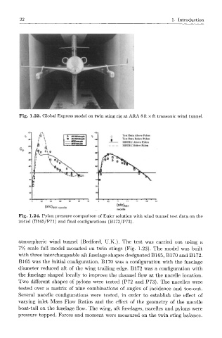
Fig. 1.23. Global Express model on twin sting rig at ARA 8 ft x ft transonic wind tunnel.
MKUMM*.! C, Test Data Above Pylon
Test Data Below Pylon
MBTEC Above Pylon
MBTLC Below Pylon
(x/c) N61
(x/c) N
nacelle
Fig. 1.24. Pylon pressure comparison of Euler solution with wind tunnel test data on the
initial (B165/P71) and final configurations (B172/P73).
atmospheric wind tunnel (Bedford, U.K.). The test was carried out using a
7% scale full model mounted on twin stings (Fig. 1.23). The model was built
with three interchangeable aft fuselage shapes designated B165, B170 and B172.
B165 was the initial configuration. B170 was a configuration with the fuselage
diameter reduced aft of the wing trailing edge. B172 was a configuration with
the fuselage shaped locally to improve the channel flow at the nacelle location.
Two different shapes of pylons were tested (P72 and P73). The nacelles were
tested over a matrix of nine combinations of angles of incidence and toe-out.
Several nacelle configurations were tested, in order to establish the effect of
varying inlet Mass Flow Ratios and the effect of the geometry of the nacelle
boat-tail on the fuselage flow. The wing, aft fuselages, nacelles and pylons were
pressure tapped. Forces and moment were measured on the twin sting balance.