
Page 42 - Computational Fluid Dynamics for Engineers
P. 42
1.4 Prediction of Aircraft Performance Degradation Due to Icing 27
continuous phases; the process involves convective heat transfer which is again
linked to the shape of the body and the nature of the flow around it. It is evident,
therefore, that a mathematical description of the phenomenon of ice formation
and its effects on lift and drag requires the solution of time-dependent equations,
albeit with comparatively large time scales, with consideration of conservation
of mass, momentum and thermal energy and with a model to represent the ice
accretion process. In addition, since the flow is turbulent under practically all
conditions, the solution of the conservation equations discussed in Chapter 2
requires a closure model with roughness effects. As discussed in Section 8.3, our
understanding of turbulent flows on surfaces with roughness and our ability to
model them is rather limited, even for geometries less complicated than those
with ice. For these reasons, prediction of ice accretion is not just a matter of
solving the known conservation equations, as discussed in [23].
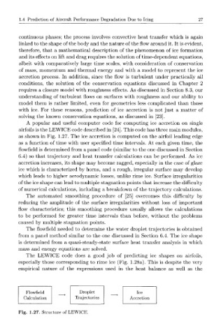
A popular and useful computer code for computing ice accretion on single
airfoils is the LEWICE code described in [24]. This code has three main modules,
as shown in Fig. 1.27. The ice accretion is computed on the airfoil leading edge
as a function of time with user specified time intervals. At each given time, the
flowfield is determined from a panel code (similar to the one discussed in Section
6.4) so that trajectory and heat transfer calculations can be performed. As ice
accretion increases, its shape may become ragged, especially in the case of glaze
ice which is characterized by horns, and a rough, irregular surface may develop
which leads to higher aerodynamic losses, unlike rime ice. Surface irregularities
of the ice shape can lead to multiple stagnation points that increase the difficulty
of numerical calculations, including a breakdown of the trajectory calculations.
The automated smoothing procedure of [25] overcomes this difficulty by
reducing the amplitude of the surface irregularities without loss of important
flow characteristics; this smoothing procedure usually allows the calculations
to be performed for greater time intervals than before, without the problems
caused by multiple stagnation points.
The flowfield needed to determine the water droplet trajectories is obtained
from a panel method similar to the one discussed in Section 6.4. The ice shape
is determined from a quasi-steady-state surface heat transfer analysis in which
mass and energy equations are solved.
The LEWICE code does a good job of predicting ice shapes on airfoils,
especially those corresponding to rime ice (Fig. 1.28a). This is despite the very
empirical nature of the expressions used in the heat balance as well as the
Flowfield Droplet Ice
Calculation Trajectories Accretion
Fig. 1.27. Structure of LEWICE.