
Page 173 - Computational Modeling in Biomedical Engineering and Medical Physics
P. 173
162 Computational Modeling in Biomedical Engineering and Medical Physics
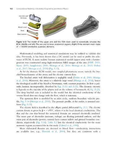
Figure 5.13 The model of the upper arm and the FEM mesh used to numerically simulate the
BCVI: (Middle and left) The arm and its inner anatomical regions; (Right) Finite element mesh made
of B130,000 tetrahedral, quadratic elements.
Mathematical modeling and numerical simulations may be utilized to validate this
idea. Previously, it has been shown that a DC model can be used to probe the rele-
vance of ECM. A more realistic human anatomical model (upper arm) with a hetero-
geneous was constructed using high-resolution MRI images of the arm (VHP, 2019;
Slicer, 2019; Simpleware, 2010; Morega et al., 2010; Morega et al., 2013; Dobre
et al., 2017; Morega et al., 2018)(Fig. 5.13).
As for the thoracic ECM model, two coupled phenomena occur, namely the bra-
chial hemodynamic of the artery and the electric current flow.
The brachial artery wall deformation is negligibly small (Dobre et al., 2010; Morega
et al., 2010). Moreover, this artery is a relatively large vessel (Morega et al., 2016), hence
the rheological model of the blood is Newtonian, with constant properties. Its flow is pul-
satile, laminar, incompressible, described by Eqs. (5.21) and (5.22). The dynamic viscosity
η depends on the viscosity of the plasma and on the volume of hematocrit, H, Eq. (5.23).
The deep brachial vein is included in the model but the electrical conductivity of the
venous blood does not change with the flow, which is stationary.
The upstream flow is modeled by an inlet cyclic, uniform boundary velocity pro-
file, Fig. 5.14 (Morega et al., 2018). The pressure profile, at the outlet, is assumed uni-
form (Fig. 5.15).
The electric field is described by the elliptic partial differential Eq. (5.1).The electric
current density is given by J 52 σrV,where σ is the local electrical conductivity. The
skin and the cuts that bound the numerical domain are assumed electrically insulated.
The inner pair of electrodes (measure, voltage) are floating potential surfaces, and the
outer pair of electrodes (power, current) have current inflow and ground boundary con-
ditions, respectively (Fig. 5.16). Table 5.2 lists the electrical conductivity for the main
anatomic regions accounted for in this study (Gabriel et al., 1996).
More elaborated theories are devoted to blood flow—conductivity interactions
are available (see, e.g., Hoetink et al., 2004), but they are consistent with a