
Page 220 -
P. 220
188 CHAPTER 6 / EXTERNAL MEMORY
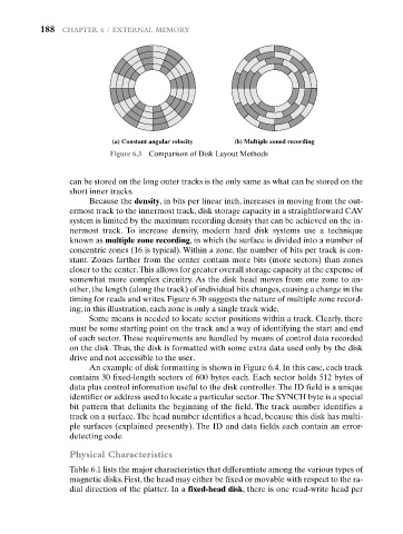
(a) Constant angular velocity (b) Multiple zoned recording
Figure 6.3 Comparison of Disk Layout Methods
can be stored on the long outer tracks is the only same as what can be stored on the
short inner tracks.
Because the density, in bits per linear inch, increases in moving from the out-
ermost track to the innermost track, disk storage capacity in a straightforward CAV
system is limited by the maximum recording density that can be achieved on the in-
nermost track. To increase density, modern hard disk systems use a technique
known as multiple zone recording, in which the surface is divided into a number of
concentric zones (16 is typical). Within a zone, the number of bits per track is con-
stant. Zones farther from the center contain more bits (more sectors) than zones
closer to the center.This allows for greater overall storage capacity at the expense of
somewhat more complex circuitry. As the disk head moves from one zone to an-
other, the length (along the track) of individual bits changes, causing a change in the
timing for reads and writes. Figure 6.3b suggests the nature of multiple zone record-
ing; in this illustration, each zone is only a single track wide.
Some means is needed to locate sector positions within a track. Clearly, there
must be some starting point on the track and a way of identifying the start and end
of each sector. These requirements are handled by means of control data recorded
on the disk. Thus, the disk is formatted with some extra data used only by the disk
drive and not accessible to the user.
An example of disk formatting is shown in Figure 6.4. In this case, each track
contains 30 fixed-length sectors of 600 bytes each. Each sector holds 512 bytes of
data plus control information useful to the disk controller. The ID field is a unique
identifier or address used to locate a particular sector.The SYNCH byte is a special
bit pattern that delimits the beginning of the field. The track number identifies a
track on a surface. The head number identifies a head, because this disk has multi-
ple surfaces (explained presently). The ID and data fields each contain an error-
detecting code.
Physical Characteristics
Table 6.1 lists the major characteristics that differentiate among the various types of
magnetic disks. First, the head may either be fixed or movable with respect to the ra-
dial direction of the platter. In a fixed-head disk, there is one read-write head per