
Page 224 -
P. 224
192 CHAPTER 6 / EXTERNAL MEMORY
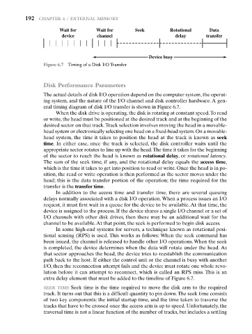
Wait for Wait for Seek Rotational Data
device channel delay transfer
Device busy
Figure 6.7 Timing of a Disk I/O Transfer
Disk Performance Parameters
The actual details of disk I/O operation depend on the computer system, the operat-
ing system, and the nature of the I/O channel and disk controller hardware. A gen-
eral timing diagram of disk I/O transfer is shown in Figure 6.7.
When the disk drive is operating, the disk is rotating at constant speed.To read
or write, the head must be positioned at the desired track and at the beginning of the
desired sector on that track.Track selection involves moving the head in a movable-
head system or electronically selecting one head on a fixed-head system.On a movable-
head system, the time it takes to position the head at the track is known as seek
time. In either case, once the track is selected, the disk controller waits until the
appropriate sector rotates to line up with the head.The time it takes for the beginning
of the sector to reach the head is known as rotational delay, or rotational latency.
The sum of the seek time, if any, and the rotational delay equals the access time,
which is the time it takes to get into position to read or write. Once the head is in po-
sition, the read or write operation is then performed as the sector moves under the
head; this is the data transfer portion of the operation; the time required for the
transfer is the transfer time.
In addition to the access time and transfer time, there are several queuing
delays normally associated with a disk I/O operation. When a process issues an I/O
request, it must first wait in a queue for the device to be available. At that time, the
device is assigned to the process. If the device shares a single I/O channel or a set of
I/O channels with other disk drives, then there may be an additional wait for the
channel to be available.At that point, the seek is performed to begin disk access.
In some high-end systems for servers, a technique known as rotational posi-
tional sensing (RPS) is used. This works as follows: When the seek command has
been issued, the channel is released to handle other I/O operations. When the seek
is completed, the device determines when the data will rotate under the head. As
that sector approaches the head, the device tries to reestablish the communication
path back to the host. If either the control unit or the channel is busy with another
I/O, then the reconnection attempt fails and the device must rotate one whole revo-
lution before it can attempt to reconnect, which is called an RPS miss. This is an
extra delay element that must be added to the timeline of Figure 6.7.
SEEK TIME Seek time is the time required to move the disk arm to the required
track. It turns out that this is a difficult quantity to pin down.The seek time consists
of two key components: the initial startup time, and the time taken to traverse the
tracks that have to be crossed once the access arm is up to speed. Unfortunately, the
traversal time is not a linear function of the number of tracks, but includes a settling