
Page 219 -
P. 219
6.1 / MAGNETIC DISK 187
Sectors Tracks
Intersector gap
Intertrack gap
S6 • • •
S6 • • •
S5 SN SN
S5
S4 S1 S1
S4 S3 S2
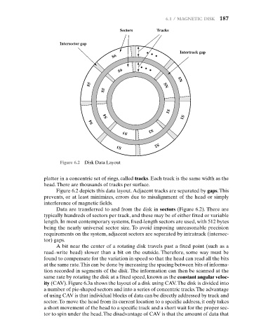
Figure 6.2 Disk Data Layout S3 S2
platter in a concentric set of rings, called tracks. Each track is the same width as the
head.There are thousands of tracks per surface.
Figure 6.2 depicts this data layout.Adjacent tracks are separated by gaps.This
prevents, or at least minimizes, errors due to misalignment of the head or simply
interference of magnetic fields.
Data are transferred to and from the disk in sectors (Figure 6.2). There are
typically hundreds of sectors per track, and these may be of either fixed or variable
length. In most contemporary systems, fixed-length sectors are used, with 512 bytes
being the nearly universal sector size. To avoid imposing unreasonable precision
requirements on the system, adjacent sectors are separated by intratrack (intersec-
tor) gaps.
A bit near the center of a rotating disk travels past a fixed point (such as a
read–write head) slower than a bit on the outside. Therefore, some way must be
found to compensate for the variation in speed so that the head can read all the bits
at the same rate.This can be done by increasing the spacing between bits of informa-
tion recorded in segments of the disk. The information can then be scanned at the
same rate by rotating the disk at a fixed speed, known as the constant angular veloc-
ity (CAV). Figure 6.3a shows the layout of a disk using CAV.The disk is divided into
a number of pie-shaped sectors and into a series of concentric tracks.The advantage
of using CAV is that individual blocks of data can be directly addressed by track and
sector.To move the head from its current location to a specific address, it only takes
a short movement of the head to a specific track and a short wait for the proper sec-
tor to spin under the head.The disadvantage of CAV is that the amount of data that