
Page 308 -
P. 308
6.2 Pose estimation 287
y (3) y (2) y (1)
x i f C(x) = Kx f P(x) = p/z f R(x) = Rx f T(x) = x-c p i
k q j c j
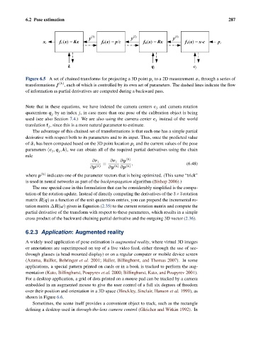
Figure 6.5 A set of chained transforms for projecting a 3D point p to a 2D measurement x i through a series of
i
transformations f (k) , each of which is controlled by its own set of parameters. The dashed lines indicate the flow
of information as partial derivatives are computed during a backward pass.
Note that in these equations, we have indexed the camera centers c j and camera rotation
quaternions q by an index j, in case more than one pose of the calibration object is being
j
used (see also Section 7.4.) We are also using the camera center c j instead of the world
translation t j , since this is a more natural parameter to estimate.
The advantage of this chained set of transformations is that each one has a simple partial
derivative with respect both to its parameters and to its input. Thus, once the predicted value
of ˜x i has been computed based on the 3D point location p and the current values of the pose
i
parameters (c j , q , k), we can obtain all of the required partial derivatives using the chain
j
rule
∂r i ∂y (k)
∂r i
= , (6.48)
∂p (k) ∂y (k) ∂p (k)
where p (k) indicates one of the parameter vectors that is being optimized. (This same “trick”
is used in neural networks as part of the backpropagation algorithm (Bishop 2006).)
The one special case in this formulation that can be considerably simplified is the compu-
tation of the rotation update. Instead of directly computing the derivatives of the 3×3 rotation
matrix R(q) as a function of the unit quaternion entries, you can prepend the incremental ro-
tation matrix ΔR(ω) given in Equation (2.35) to the current rotation matrix and compute the
partial derivative of the transform with respect to these parameters, which results in a simple
cross product of the backward chaining partial derivative and the outgoing 3D vector (2.36).
6.2.3 Application: Augmented reality
A widely used application of pose estimation is augmented reality, where virtual 3D images
or annotations are superimposed on top of a live video feed, either through the use of see-
through glasses (a head-mounted display) or on a regular computer or mobile device screen
(Azuma, Baillot, Behringer et al. 2001; Haller, Billinghurst, and Thomas 2007). In some
applications, a special pattern printed on cards or in a book is tracked to perform the aug-
mentation (Kato, Billinghurst, Poupyrev et al. 2000; Billinghurst, Kato, and Poupyrev 2001).
For a desktop application, a grid of dots printed on a mouse pad can be tracked by a camera
embedded in an augmented mouse to give the user control of a full six degrees of freedom
over their position and orientation in a 3D space (Hinckley, Sinclair, Hanson et al. 1999), as
shown in Figure 6.6.
Sometimes, the scene itself provides a convenient object to track, such as the rectangle
defining a desktop used in through-the-lens camera control (Gleicher and Witkin 1992). In