
Page 311 -
P. 311
290 6 Feature-based alignment
(a) (b)
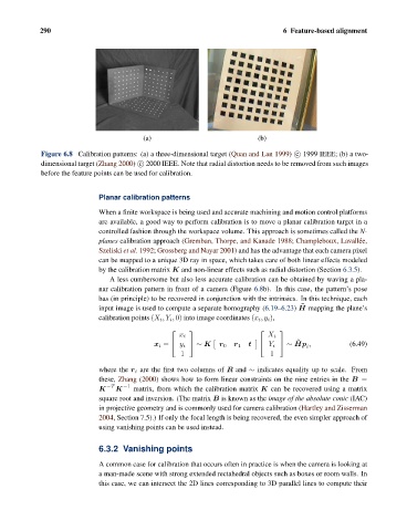
Figure 6.8 Calibration patterns: (a) a three-dimensional target (Quan and Lan 1999) c 1999 IEEE; (b) a two-
dimensional target (Zhang 2000) c 2000 IEEE. Note that radial distortion needs to be removed from such images
before the feature points can be used for calibration.
Planar calibration patterns
When a finite workspace is being used and accurate machining and motion control platforms
are available, a good way to perform calibration is to move a planar calibration target in a
controlled fashion through the workspace volume. This approach is sometimes called the N-
planes calibration approach (Gremban, Thorpe, and Kanade 1988; Champleboux, Lavall´ ee,
Szeliski et al. 1992; Grossberg and Nayar 2001) and has the advantage that each camera pixel
can be mapped to a unique 3D ray in space, which takes care of both linear effects modeled
by the calibration matrix K and non-linear effects such as radial distortion (Section 6.3.5).
A less cumbersome but also less accurate calibration can be obtained by waving a pla-
nar calibration pattern in front of a camera (Figure 6.8b). In this case, the pattern’s pose
has (in principle) to be recovered in conjunction with the intrinsics. In this technique, each
˜
input image is used to compute a separate homography (6.19–6.23) H mapping the plane’s
calibration points (X i ,Y i , 0) into image coordinates (x i ,y i ),
⎡ ⎤ ⎡ ⎤
x i X i
˜
x i = ⎣ y i ⎦ ∼ K r 0 r 1 t ⎣ Y i ⎦ ∼ Hp , (6.49)
i
1 1
where the r i are the first two columns of R and ∼ indicates equality up to scale. From
these, Zhang (2000) shows how to form linear constraints on the nine entries in the B =
−T −1
K K matrix, from which the calibration matrix K can be recovered using a matrix
square root and inversion. (The matrix B is known as the image of the absolute conic (IAC)
in projective geometry and is commonly used for camera calibration (Hartley and Zisserman
2004, Section 7.5).) If only the focal length is being recovered, the even simpler approach of
using vanishing points can be used instead.
6.3.2 Vanishing points
A common case for calibration that occurs often in practice is when the camera is looking at
a man-made scene with strong extended rectahedral objects such as boxes or room walls. In
this case, we can intersect the 2D lines corresponding to 3D parallel lines to compute their