
Page 310 -
P. 310
6.3 Geometric intrinsic calibration 289
(a) (b)
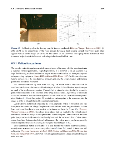
Figure 6.7 Calibrating a lens by drawing straight lines on cardboard (Debevec, Wenger, Tchou et al. 2002) c
2002 ACM: (a) an image taken by the video camera showing a hand holding a metal ruler whose right edge
appears vertical in the image; (b) the set of lines drawn on the cardboard converging on the front nodal point
(center of projection) of the lens and indicating the horizontal field of view.
6.3.1 Calibration patterns
The use of a calibration pattern or set of markers is one of the more reliable ways to estimate
a camera’s intrinsic parameters. In photogrammetry, it is common to set up a camera in a
large field looking at distant calibration targets whose exact location has been precomputed
using surveying equipment (Slama 1980; Atkinson 1996; Kraus 1997). In this case, the trans-
lational component of the pose becomes irrelevant and only the camera rotation and intrinsic
parameters need to be recovered.
If a smaller calibration rig needs to be used, e.g., for indoor robotics applications or for
mobile robots that carry their own calibration target, it is best if the calibration object can span
as much of the workspace as possible (Figure 6.8a), as planar targets often fail to accurately
predict the components of the pose that lie far away from the plane. A good way to determine
if the calibration has been successfully performed is to estimate the covariance in the param-
eters (Section 6.1.4) and then project 3D points from various points in the workspace into the
image in order to estimate their 2D positional uncertainty.
An alternative method for estimating the focal length and center of projection of a lens
is to place the camera on a large flat piece of cardboard and use a long metal ruler to draw
lines on the cardboard that appear vertical in the image, as shown in Figure 6.7a(Debevec,
Wenger, Tchou et al. 2002). Such lines lie on planes that are parallel to the vertical axis of
the camera sensor and also pass through the lens’ front nodal point. The location of the nodal
point (projected vertically onto the cardboard plane) and the horizontal field of view (deter-
mined from lines that graze the left and right edges of the visible image) can be recovered by
intersecting these lines and measuring their angular extent (Figure 6.7b).
If no calibration pattern is available, it is also possible to perform calibration simulta-
neously with structure and pose recovery (Sections 6.3.4 and 7.4), which is known as self-
calibration (Faugeras, Luong, and Maybank 1992; Hartley and Zisserman 2004; Moons, Van
Gool, and Vergauwen 2010). However, such an approach requires a large amount of imagery
to be accurate.