
Page 122 - Corrosion Engineering Principles and Practice
P. 122
96 C h a p t e r 5 C o r r o s i o n K i n e t i c s a n d A p p l i c a t i o n s o f E l e c t r o c h e m i s t r y 97
can be made of any material provided it is inert to the electrolytic
environment. It basically consists of a bent tube generally filled with
the test solution with a large enough opening to accommodate a ref-
erence electrode at one end and a usually much smaller opening at
the other end to provide diffusional movement of the electrolyte.
5.4.2 Soil Resistivity Measurements
Soil resistivity is a function of soil moisture and the concentrations of
ionic soluble salts and is considered to be the most comprehensive
indicator of a soil’s corrosivity. Typically, the lower the resistivity, the
higher will be the corrosivity as discussed in more details in Chap. 10.
Typically, soil resistivity decreases with increasing water content and
the concentration of ionic species. Sandy soils, for example, are high
up on the resistivity scale and therefore considered the least corrosive
while clay soils are excellent at retaining water and at the opposite
end of the corrosivity spectrum.
Four-Pin Method (Wenner Method)
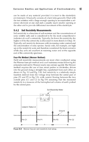
Field soil resistivity measurements are most often conducted using
the Wenner four-pin method and a soil resistance meter following the
principles laid out by Wenner nearly one century ago [2]. The Wenner
method requires the use of four metal probes or electrodes, driven
into the ground along a straight line, equidistant from each other, as
shown in Fig. 5.9 and Fig. 5.10. Soil resistivity is a relatively simple
function derived from the voltage drop between the center pair of
pins (P1 and P2 in Fig 5.9), with current flowing between the two
outside pins (C1 and C2 in Fig 5.9) assuming that the measured
resistivity is a measure of the hemispherical volume of earth probed
by the central pins.
Soil Resistivity Meter
C1 C2
P1 P2
Listed in Table 2.2
Ground
Pin C1 Pin P1 Pin P2 Pin C2
a
FIGURE 5.9 Wenner four-pin soil resistivity test setup.