
Page 121 - Corrosion Engineering Principles and Practice
P. 121
96 C h a p t e r 5 C o r r o s i o n K i n e t i c s a n d A p p l i c a t i o n s o f E l e c t r o c h e m i s t r y 97
Other geometries would require the calculation of appropriate cell
constants. The cell constant of an electrochemical cell with two
concentric tubes as electrodes would be, for example, expressed by
Eq. (5.17). Such an arrangement is a common design in the production
of domestic water heaters in which a central sacrificial magnesium
anode is inserted typically in the center of the hot-water tank to
protect the surrounding tank material.
1 r 2
Cell constant = 2πh ln (5.17)
1
r
where h is the height of the cylindrical tank
r is the internal tank radius
2
r is the radius of the sacrificial anode
1
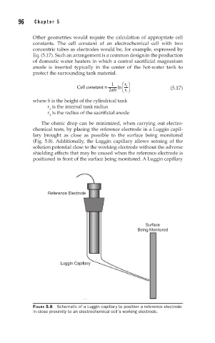
The ohmic drop can be minimized, when carrying out electro-
chemical tests, by placing the reference electrode in a Luggin capil-
lary brought as close as possible to the surface being monitored
(Fig. 5.8). Additionally, the Luggin capillary allows sensing of the
solution potential close to the working electrode without the adverse
shielding effects that may be caused when the reference electrode is
positioned in front of the surface being monitored. A Luggin capillary
Reference Electrode
Surface
Being Monitored
Luggin Capillary
FIGURE 5.8 Schematic of a Luggin capillary to position a reference electrode
in close proximity to an electrochemical cell’s working electrode.