Page 120 - Corrosion Engineering Principles and Practice
P. 120

94   C h a p t e r   5     C o r r o s i o n   K i n e t i c s   a n d   A p p l i c a t i o n s   o f   E l e c t r o c h e m i s t r y    95


                                                          q
                       Water                            (W cm)
                       Pure water                       20,000,000
                       Distilled water                  500,000
                       Rain water                       20,000
                       Tap water                        1000–5000
                       River water (brackish)           200
                       Sea-water (coastal)              30
                       Sea-water (open sea)             20–25

                      TABLE 5.4  Resistivity of Some Typical Waters

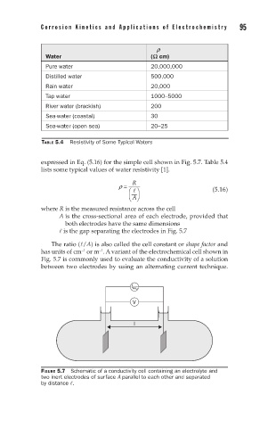
                      expressed in Eq. (5.16) for the simple cell shown in Fig. 5.7. Table 5.4
                      lists some typical values of water resistivity [1].
                                                  R
                                              r =
                                                                        (5.16)
                                                  
                                                  A
                                                 
                      where R is the measured resistance across the cell
                            A  is the cross-sectional area of each electrode, provided that
                             both electrodes have the same dimensions
                             is the gap separating the electrodes in Fig. 5.7
                         The ratio (/A) is also called the cell constant or shape factor and
                      has units of cm  or m . A variant of the electrochemical cell shown in
                                        −1
                                  −1
                      Fig. 5.7 is commonly used to evaluate the conductivity of a solution
                      between two electrodes by using an alternating current technique.
                                                  I AC

                                                  V


                                                   l


                      FIGURE 5.7  Schematic of a conductivity cell containing an electrolyte and
                      two inert electrodes of surface A parallel to each other and separated
                      by distance .
   115   116   117   118   119   120   121   122   123   124   125