
Page 126 - Corrosion Engineering Principles and Practice
P. 126
100 C h a p t e r 5 C o r r o s i o n K i n e t i c s a n d A p p l i c a t i o n s o f E l e c t r o c h e m i s t r y 101
Instrument
3000 Ohm cm
0.3 m
Augered holes
(If required)
Iron tip
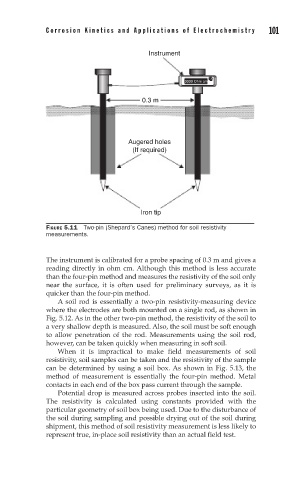
FIGURE 5.11 Two-pin (Shepard’s Canes) method for soil resistivity
measurements.
The instrument is calibrated for a probe spacing of 0.3 m and gives a
reading directly in ohm cm. Although this method is less accurate
than the four-pin method and measures the resistivity of the soil only
near the surface, it is often used for preliminary surveys, as it is
quicker than the four-pin method.
A soil rod is essentially a two-pin resistivity-measuring device
where the electrodes are both mounted on a single rod, as shown in
Fig. 5.12. As in the other two-pin method, the resistivity of the soil to
a very shallow depth is measured. Also, the soil must be soft enough
to allow penetration of the rod. Measurements using the soil rod,
however, can be taken quickly when measuring in soft soil.
When it is impractical to make field measurements of soil
resistivity, soil samples can be taken and the resistivity of the sample
can be determined by using a soil box. As shown in Fig. 5.13, the
method of measurement is essentially the four-pin method. Metal
contacts in each end of the box pass current through the sample.
Potential drop is measured across probes inserted into the soil.
The resistivity is calculated using constants provided with the
particular geometry of soil box being used. Due to the disturbance of
the soil during sampling and possible drying out of the soil during
shipment, this method of soil resistivity measurement is less likely to
represent true, in-place soil resistivity than an actual field test.