
Page 568 - Corrosion Engineering Principles and Practice
P. 568
530 C h a p t e r 1 3 C a t h o d i c P r o t e c t i o n 531
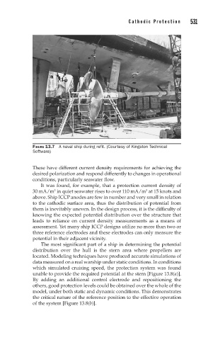
FIGURE 13.7 A naval ship during refit. (Courtesy of Kingston Technical
Software)
These have different current density requirements for achieving the
desired polarization and respond differently to changes in operational
conditions, particularly seawater flow.
It was found, for example, that a protection current density of
30 mA/m in quiet seawater rises to over 110 mA/m at 15 knots and
2
2
above. Ship ICCP anodes are few in number and very small in relation
to the cathodic surface area, thus the distribution of potential from
them is inevitably uneven. In the design process, it is the difficulty of
knowing the expected potential distribution over the structure that
leads to reliance on current density measurements as a means of
assessment. Yet many ship ICCP designs utilize no more than two or
three reference electrodes and these electrodes can only measure the
potential in their adjacent vicinity.
The most significant part of a ship in determining the potential
distribution over the hull is the stern area where propellers are
located. Modeling techniques have produced accurate simulations of
data measured on a real warship under static conditions. In conditions
which simulated cruising speed, the protection system was found
unable to provide the required potential at the stern [Figure 13.8(a)].
By adding an additional control electrode and repositioning the
others, good protection levels could be obtained over the whole of the
model, under both static and dynamic conditions. This demonstrates
the critical nature of the reference position to the effective operation
of the system [Figure 13.8(b)].