
Page 571 - Corrosion Engineering Principles and Practice
P. 571
534 C h a p t e r 1 3 C a t h o d i c P r o t e c t i o n 535
Groundbed
Rectifier
+
–
I A I A I A I A
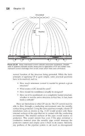
FIGURE 13.10 Basic impressed current cathodic protection installation. Shaded
area on pipeline indicates anodic areas prior to application of CP and dotted lines
represent current discharge from anodic areas which have been eliminated.
normal function of the structure being protected. While the basic
principle of applying CP is quite simple, some practical questions
have to be resolved, such as
• How much minimum current is needed to protect a given
structure?
• What source of DC should be used?
• How should the installation actually be designed?
• How can it be ascertained, on a completely buried structure,
whether or not the entire structure surface has, in fact, been
made a cathode?
There are limitations to what CP can do. The CP current must be
able to flow through a conducting environment onto the metallic
surface being protected. Using the same pipeline example, a basic CP
installation such as shown in Fig. 13.10 would protect only those
external surfaces of the pipe that are in contact with the conducting
environment. The internal surfaces of the pipe would receive no
protection. This would remain true even if the pipe contained a
conductive material since the metallic pipe would intercept the
protective current and simply carry it back to its source. Similarly,
any portions of the pipeline system in air (such as aboveground