
Page 567 - Corrosion Engineering Principles and Practice
P. 567
530 C h a p t e r 1 3 C a t h o d i c P r o t e c t i o n 531
adjacent to the anodes, where the concentration of hydroxyl ions may
be very high. In addition, the high local currents around the anodes
may reduce the protection supplied to the rest of the structure.
On a supertanker, the initial current of 10 A may rise to over
1000 A during the course of its operational life. Modern ICCP ship
designs usually place anodes in symmetrical dispositions, but in
bulk carriers, there is a need for internal access and for cable-runs
to be away from anodes and reference electrodes. This usually
precludes electrodes from being sited external to storage tanks.
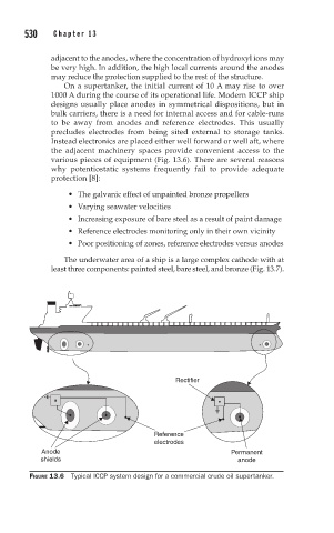
Instead electronics are placed either well forward or well aft, where
the adjacent machinery spaces provide convenient access to the
various pieces of equipment (Fig. 13.6). There are several reasons
why potentiostatic systems frequently fail to provide adequate
protection [8]:
• The galvanic effect of unpainted bronze propellers
• Varying seawater velocities
• Increasing exposure of bare steel as a result of paint damage
• Reference electrodes monitoring only in their own vicinity
• Poor positioning of zones, reference electrodes versus anodes
The underwater area of a ship is a large complex cathode with at
least three components: painted steel, bare steel, and bronze (Fig. 13.7).
Rectifier
Reference
electrodes
Anode Permanent
shields anode
FIGURE 13.6 Typical ICCP system design for a commercial crude oil supertanker.