
Page 22 - DSP Integrated Circuits
P. 22
1.5 DSP Systems 7
high work loads. The former may be found in battery-powered applications (for
example, mobile phones), while the latter are typical for many video applications
because of their high sample rates. This approach yields very high performance at
the cost of a somewhat larger design effort compared to the two approaches dis-
cussed earlier.
1.5 DSP SYSTEMS
Generally, a system provides an end-user with a complete service. For example, a
CD player with amplifier and loudspeakers is a system with three components.
The components in a system are often incorrectly referred to as systems or sub-
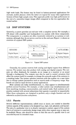
systems, although they do not prove a service to the end-user. Figure 1.4 shows an
overview of a typical DSP system.
Figure 1.4 Typical DSP system
Generally, the system receives both analog and digital inputs from different
sources. The system may also produce both analog and digital outputs. The out-
puts are often displayed, for example, as an image on a monitor or as sound
through a loudspeaker. The outputs may also be used to control actuators that
affect the system itself, for example, to change the azimuth angle of the antenna in
a tracking radar. The system operator interacts with the system via a user inter-
face to change system parameters such as search mode or frequency range. Key-
boards are used as input devices in many applications.
Most systems are today multifunctional, i.e., they appear to simultaneously
perform several functions. For example, a radar system may simultaneously per-
form searching, tracking, communication, and control tasks. Such systems are in
practice realized with several subsystems that operate in parallel or sequentially.
Often these subsystems are designed to perform only a single function and are
referred to as fixed-function subsystems.
1.5.1 Facets
Several different representations, called views or facets, are needed to describe
various aspects of the system to be designed (e.g., logic, test, physical, and layout).
The aim of a particular view is to clearly represent a certain aspect of the system
that is of interest in a particular design stage while other aspects may, or may not,
be modeled. Hence, care should be taken so that the use of a specific view is not
extended beyond its intended scope.